VEHICLE STABILITY CONTROL SYSTEM Skid Control Buzzer Circuit
DESCRIPTION
A buzzer sounds to alert the driver when the vehicle-to-vehicle distance becomes less than the set value (for vehicles with a dynamic radar cruise control).
WIRING DIAGRAM
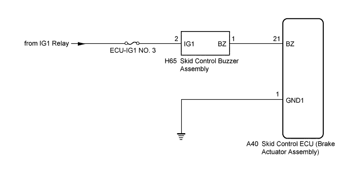
INSPECTION PROCEDURE
Note
When replacing the skid control ECU (brake actuator assembly), perform zero point calibration Click here.
PROCEDURE
-
CHECK BUZZER OPERATION
-
Confirm problem symptoms of the skid control buzzer assembly according to the customer problem analysis.
Result Result Proceed to Buzzer does not sound. A Buzzer sounds constantly. B
B 
INSPECT BRAKE ACTUATOR ASSEMBLY Click here
A 
-
-
PERFORM ACTIVE TEST USING GTS (SKID CONTROL BUZZER ASSEMBLY)
-
Connect the GTS to the DLC3.
-
Turn the engine switch on (IG).
-
Select the Active Test on the GTS Click here.
ABS/VSC/TRC Tester Display Test Part Control Range Diagnostic Note DSS Signal Buzzer Skid control buzzer assembly Buzzer ON/OFF Buzzer can be heard -
Check that the buzzer sounds/stops when turning the skid control buzzer assembly on/off using the GTS.
Result Result Proceed to Buzzer does not sound. A Buzzer sounds/stops. B Tech Tips
If troubleshooting has been carried out according to Problem Symptoms Table, refer back to the table and proceed to the next step Click here.
B 
USE SIMULATION METHOD TO CHECK Click here
A
-
-
CHECK HARNESS AND CONNECTOR (POWER SOURCE TERMINAL)
-
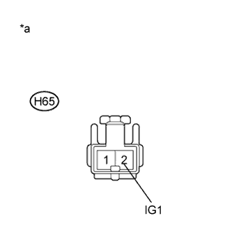
Text in Illustration *a Front view of wire harness connector
(to Skid Control Buzzer Assembly)
Turn the engine switch off.
-
Disconnect the H65 skid control buzzer assembly connector.
-
Turn the engine switch on (IG).
-
Measure the voltage according to the value(s) in the table below.
Standard Voltage Tester Connection Condition Specified Condition H65-2 (IG1) - Body ground Engine switch on (IG) 11 to 14 V
NG
REPAIR OR REPLACE HARNESS OR CONNECTOR (POWER SOURCE CIRCUIT)
OK
-
-
INSPECT SKID CONTROL BUZZER ASSEMBLY
-
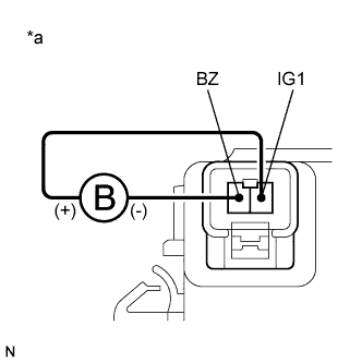
Text in Illustration *a Component without harness connected
(Skid Control Buzzer Assembly)
Turn the engine switch off.
-
Connect a negative (-) lead from the battery to terminal 1 (BZ), and a positive (+) lead to terminal 2 (IG1) of the skid control buzzer assembly, and then check that the buzzer sounds.
OK The skid control buzzer assembly sounds.
NG
REPLACE SKID CONTROL BUZZER ASSEMBLY Click here
OK
-
-
CHECK HARNESS AND CONNECTOR (BRAKE ACTUATOR ASSEMBLY - SKID CONTROL BUZZER ASSEMBLY)
-
Disconnect the A40 skid control ECU (brake actuator assembly) connector.
-
Measure the resistance according to the value(s) in the table below.
Standard Resistance Tester Connection Condition Specified Condition A40-21 (BZ) - H65-1 (BZ) Always Below 1 Ω A40-21 (BZ) - Body ground Always 10 kΩ or higher
NG
REPAIR OR REPLACE HARNESS OR CONNECTOR
OK
-
-
CHECK HARNESS AND CONNECTOR (GND1 TERMINAL)
-
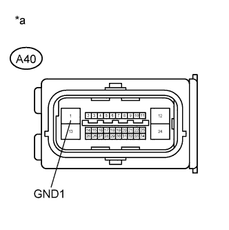
Text in Illustration *a Front view of wire harness connector
(to Skid Control ECU (Brake Actuator Assembly))
Measure the resistance according to the value(s) in the table below.
Standard Resistance Tester Connection Condition Specified Condition A40-1 (GND1) - Body ground Always Below 1 Ω Tech Tips
If troubleshooting has been carried out according to Problem Symptoms Table, refer back to the table and proceed to the next step before replacing the part Click here.
NG
REPAIR OR REPLACE HARNESS OR CONNECTOR (GND1 CIRCUIT)
OK 
REPLACE BRAKE ACTUATOR ASSEMBLY Click here
-
-
INSPECT BRAKE ACTUATOR ASSEMBLY
-
Disconnect the A40 skid control ECU (brake actuator assembly) connector.
-
Check the skid control buzzer assembly operation.
Result Result Proceed to Buzzer stops. A Buzzer sounds constantly. B Tech Tips
If troubleshooting has been carried out according to Problem Symptoms Table, refer back to the table and proceed to the next step before replacing the part Click here.
B
REPLACE SKID CONTROL BUZZER ASSEMBLY Click here
A
REPLACE BRAKE ACTUATOR ASSEMBLY Click here
-
-
REPLACE SKID CONTROL BUZZER ASSEMBLY
-
Reconnect the A40 skid control ECU (brake actuator assembly) connector.
-
Replace the skid control buzzer assembly Click here.
-
Check the skid control buzzer assembly operation.
Result Result Proceed to Buzzer stops. A Buzzer sounds constantly. B
B
CHECK IF CONNECTOR IS SECURELY CONNECTED Click here
A
END
-
-
CHECK IF CONNECTOR IS SECURELY CONNECTED
-
Gently jiggle the connectors and wire harnesses and check the skid control buzzer assembly operation.
Result Result Proceed to Buzzer stops. A Buzzer sounds constantly. B
B
REPAIR OR REPLACE HARNESS OR CONNECTOR
A
END
-