REAR LOWER ARM (for No. 1 Arm) INSTALLATION

Tech Tips
-
Use the same procedure for the RH side and LH side.
-
The procedure listed below is for the LH side.
-
TEMPORARILY TIGHTEN REAR NO. 1 SUSPENSION ARM ASSEMBLY
-
Temporarily tighten the rear No. 1 suspension arm assembly (inner side) to the rear suspension member sub-assembly with the bolt.
-
-
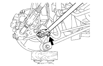
CONNECT REAR NO. 1 SUSPENSION ARM ASSEMBLY
-
Connect the rear No. 1 suspension arm assembly (outer side) to the rear axle carrier sub-assembly with the bolt and nut.
Note
When temporarily tightening the bolt, keep the nut from rotating.
Tech Tips
Insert the bolt from the front of the vehicle.
-
-
STABILIZE SUSPENSION
-
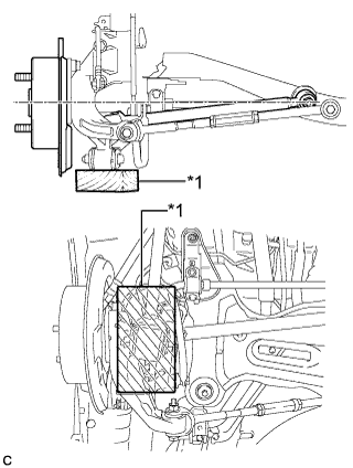
Text in Illustration *1 Wooden Block Jack up the rear axle carrier sub-assembly, placing a wooden block under it to avoid damage. Apply load to the suspension so that the installed bolt of the rear No. 1 suspension arm assembly (inner side) is horizontally aligned with the center of the rear axle hub.
CAUTION:
Do not jack up the rear axle carrier sub-assembly too high as the vehicle may fall.
Note
-
When jacking up the rear axle carrier sub-assembly, be sure to jack it up slowly.
-
Make sure to perform this operation with the vehicle kept as low as possible.
-
-
-
FULLY TIGHTEN REAR NO. 1 SUSPENSION ARM ASSEMBLY
-
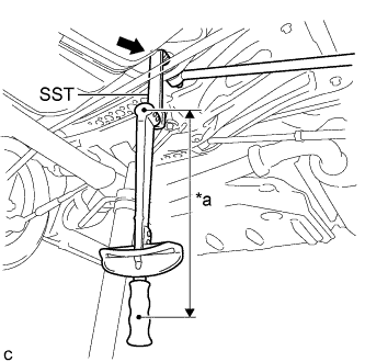
Text in Illustration *a Fulcrum Length Using SST, fully tighten the rear No. 1 suspension arm assembly (inner side) with the bolt.
- SST
- 09961-00950
- Torque:
- without SST
- 100 N*m { 1020 kgf*cm, 74 ft.*lbf }
- with SST
- 72 N*m { 731 kgf*cm, 53 ft.*lbf }
Note
-
Use a torque wrench with a fulcrum length of 380 mm (1.25 ft.).
-
This torque value is effective when SST is parallel to the torque wrench.
-
Fully tighten the rear No. 1 suspension arm assembly (outer side) with the bolt.
- Torque:
- 100 N*m { 1020 kgf*cm, 74 ft.*lbf }
Note
Since a stopper nut is used, fully tighten the bolt.
-
-
INSTALL NO. 2 FLOOR UNDER COVER
-
Install the No. 2 floor under cover with the 2 bolts, 3 nuts and 2 clips.
- Torque:
- 4.0 N*m { 41 kgf*cm, 35 in.*lbf }
-
-
INSTALL NO. 1 FLOOR UNDER COVER (for RH Side)
-
Install the No. 1 floor under cover with the 2 bolts, 3 nuts and 2 clips.
- Torque:
- 4.0 N*m { 41 kgf*cm, 35 in.*lbf }
-
-
INSTALL REAR WHEEL
- Torque:
- 103 N*m { 1049 kgf*cm, 76 ft.*lbf }
-
INSPECT AND ADJUST REAR WHEEL ALIGNMENT