FRONT LOWER SUSPENSION ARM (for 2AR-FE) INSTALLATION

-
INSTALL FRONT LOWER NO. 1 SUSPENSION ARM SUB-ASSEMBLY LH (for LH Side)
-
Install the front lower arm bushing stopper to the front lower No. 1 suspension arm sub-assembly LH.
-
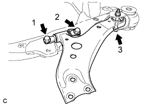
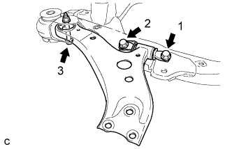
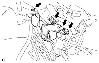
Install the front lower No. 1 suspension arm sub-assembly LH to the front frame assembly with the 3 bolts and nut in the order shown in the illustration.
- Torque:
- Bolt 1, 2
- 200 N*m { 2039 kgf*cm, 148 ft.*lbf }
- Bolt 3
- 135 N*m { 1377 kgf*cm, 100 ft.*lbf }
Note
While keeping the nut from rotating, tighten the bolt.
-
Install the front lower No. 1 suspension arm sub-assembly LH to the front lower ball joint assembly with the bolt and 2 nuts.
- Torque:
- 92 N*m { 938 kgf*cm, 68 ft.*lbf }
-
-
INSTALL ENGINE MOUNTING INSULATOR LH (for LH Side)
-
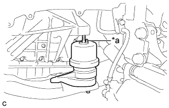
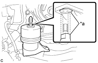
Text in Illustration *a Pin Set the engine mounting insulator LH on the front frame assembly.
-
Slowly lower the engine assembly with transaxle using a jack and a wooden block.
Note
-
Match the position of the pin (stopper).
-
Do not position the wooden block on the oil pan.
-
Do not damage the components surrounding the engine assembly with transaxle.
-
Ensure that the jack and wooden block are stable.
-
-
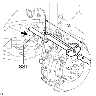
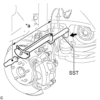
Text in Illustration *a Fulcrum Length Using SST, install the nut to the engine mounting insulator LH.
- SST
- 09961-00950
- Torque:
- without SST
- 95 N*m { 969 kgf*cm, 70 ft.*lbf }
- with SST
- 68 N*m { 695 kgf*cm, 50 ft.*lbf }
Tech Tips
-
This torque value is effective when SST is parallel to the torque wrench.
-
This torque value can be obtained by using a torque wrench with a fulcrum length of 380 mm (1.25 ft.) and SST with a fulcrum length of 150 mm (5.91 in.).
-
If using a torque wrench with a length that is not 380 mm (1.25 ft.), calculate the torque specification for the torque wrench and SST based on the "without SST" torque specification Click here.
-
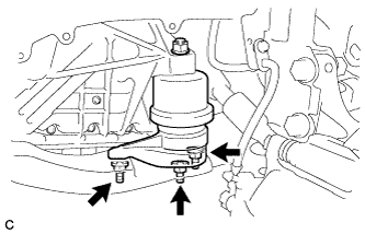
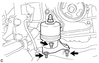
Install the engine mounting insulator LH with the 3 nuts.
- Torque:
- 87 N*m { 887 kgf*cm, 64 ft.*lbf }
-
Install the 2 hole plugs.
-
-
INSTALL FRONT LOWER NO. 1 SUSPENSION ARM SUB-ASSEMBLY RH (for RH Side)
-
Install the front lower arm bushing stopper to the front lower No. 1 suspension arm sub-assembly RH.
-
Install the front lower No. 1 suspension arm sub-assembly RH to the front frame assembly with the 3 bolts and nut in the order shown in the illustration.
- Torque:
- Bolt 1, 2
- 200 N*m { 2039 kgf*cm, 148 ft.*lbf }
- Bolt 3
- 135 N*m { 1377 kgf*cm, 100 ft.*lbf }
Note
While keeping the nut from rotating, tighten the bolt.
-
Install the front lower No. 1 suspension arm sub-assembly RH to the front lower ball joint assembly with the bolt and 2 nuts.
- Torque:
- 92 N*m { 938 kgf*cm, 68 ft.*lbf }
-
-
INSTALL ENGINE MOUNTING INSULATOR RH (for RH Side)
-
Text in Illustration *a Cutout Set the engine mounting insulator RH on the front frame assembly.
-
Slowly lower the engine assembly with transaxle using a jack and a wooden block.
Note
-
Match the position of the cutout (stopper).
-
Do not position the wooden block on the oil pan.
-
Do not damage the components surrounding the engine assembly with transaxle.
-
Ensure that the jack and wooden block are stable.
-
-
Text in Illustration *a Fulcrum Length Using SST, install the nut to the engine mounting insulator RH.
- SST
- 09961-00950
- Torque:
- without SST
- 95 N*m { 969 kgf*cm, 70 ft.*lbf }
- with SST
- 68 N*m { 695 kgf*cm, 50 ft.*lbf }
Tech Tips
-
This torque value is effective when SST is parallel to the torque wrench.
-
This torque value can be obtained by using a torque wrench with a fulcrum length of 380 mm (1.25 ft.) and SST with a fulcrum length of 150 mm (5.91 in.).
-
If using a torque wrench with a length that is not 380 mm (1.25 ft.), calculate the torque specification for the torque wrench and SST based on the "without SST" torque specification Click here.
-
Install the engine mounting insulator RH with the 3 nuts.
- Torque:
- 87 N*m { 887 kgf*cm, 64 ft.*lbf }
-
Install the 2 hole plugs.
-
-
INSTALL ENGINE MOVING CONTROL ROD BRACKET (for RH Side)
-
Temporarily install the engine moving control rod bracket with the 4 bolts.
-
Fully tighten the engine moving control rod bracket with the 4 bolts.
- Torque:
- 38 N*m { 387 kgf*cm, 28 ft.*lbf }
-
-
INSTALL NO. 2 ENGINE MOUNTING STAY RH (for RH Side)
-
Install the No. 2 engine mounting stay RH with the 2 bolts.
- Torque:
- 38 N*m { 387 kgf*cm, 28 ft.*lbf }
-
-
INSTALL EARTH WIRE (for RH Side)
-
Install the earth wire to the engine moving control rod bracket with the bolt.
- Torque:
- 8.0 N*m { 82 kgf*cm, 71 in.*lbf }
-
-
INSTALL FRONT ENGINE MOUNTING INSULATOR
-
Install the front engine mounting insulator to the front frame assembly with the 3 nuts.
- Torque:
- 52 N*m { 530 kgf*cm, 38 ft.*lbf }
-
-
CONNECT OXYGEN SENSOR
-
Connect the oxygen sensor connector.
-
-
INSTALL FRONT FENDER APRON SEAL LH (for LH Side)
-
INSTALL FRONT FENDER APRON SEAL RH (for RH Side)
-
INSTALL ENGINE UNDER COVER LH
-
INSTALL ENGINE UNDER COVER RH
-
INSTALL FRONT WHEEL OPENING EXTENSION PAD LH
-
INSTALL FRONT WHEEL OPENING EXTENSION PAD RH
-
INSTALL AIR CLEANER CASE SUB-ASSEMBLY
-
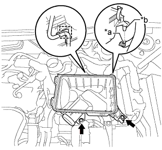
Text in Illustration *a Hole *b Projection Insert the projection of the air cleaner case sub-assembly into the hole of the No. 2 air cleaner bracket as shown in the illustration.
-
Install the 2 bolts.
- Torque:
- 5.0 N*m { 51 kgf*cm, 44 in.*lbf }
-
Connect the wire harness clamp.
-
-
INSTALL AIR CLEANER FILTER ELEMENT SUB-ASSEMBLY
-
INSTALL AIR CLEANER CAP SUB-ASSEMBLY
-
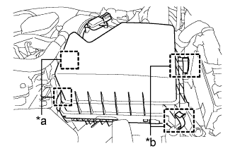
Text in Illustration *a Hinge *b Clamp Connect the 2 hinges of the air cleaner cap sub-assembly.
-
Install the air cleaner cap sub-assembly with the 2 clamps.
-
Connect the air cleaner cap sub-assembly to the throttle with motor body assembly the hose clamp.
-
Connect the ventilation hose to the cylinder head cover.
-
Install the fuel vapor feed hose to the air cleaner hose.
-
Connect the mass air flow meter connector and 2 wire harness clamps to the air cleaner cap sub-assembly.
-
Connect the vacuum switching valve assembly to the air cleaner cap sub-assembly.
-
-
INSTALL NO. 1 ENGINE COVER SUB-ASSEMBLY
-
Engage the 3 pins to install the No.1 engine cover sub-assembly.
-
-
INSTALL FRONT OUTER COWL TOP PANEL SUB-ASSEMBLY (for LHD)
-
Install the front outer cowl top panel sub-assembly with the 10 bolts.
- Torque:
- 10 N*m { 102 kgf*cm, 7 ft.*lbf }
-
Engage the 2 clamps to install the wire harness to the front outer cowl top panel sub-assembly.
-
Connect the connector to install the wire harness to the front outer cowl top panel sub-assembly.
-
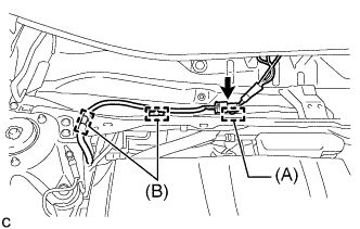
Engage the 2 clamps (B).
-
w/ Wiper Deicer System:
Engage the clamp (A).
-
-
INSTALL FRONT OUTER COWL TOP PANEL SUB-ASSEMBLY (for RHD)
-
Install the front outer cowl top panel sub-assembly with the 10 bolts.
- Torque:
- 10 N*m { 102 kgf*cm, 7 ft.*lbf }
-
Engage the 2 clamps to install the wire harness to the front outer cowl top panel sub-assembly.
-
-
INSTALL WINDSHIELD WIPER MOTOR AND LINK ASSEMBLY
-
INSTALL FRONT WHEELS
- Torque:
- 103 N*m { 1049 kgf*cm, 76 ft.*lbf }
-
CONNECT CABLE TO NEGATIVE BATTERY TERMINAL
Note
When disconnecting the cable, some systems need to be initialized after the cable is reconnected Click here.
-
INSPECT AND ADJUST FRONT WHEEL ALIGNMENT