AUTOMATIC TRANSAXLE ASSEMBLY INSTALLATION

-
INSPECT TORQUE CONVERTER ASSEMBLY
-
Inspect the one-way clutch.
-
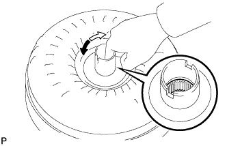
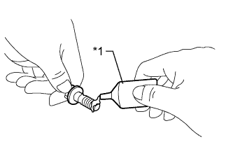
Press on the splines of the stator with a finger and rotate it. Check that it rotates smoothly when turned clockwise and rotates with difficulty when turned counterclockwise.
If necessary, clean the torque converter assembly and recheck the one-way clutch.
Replace the torque converter assembly if the one-way clutch still fails the inspection.
Text in Illustration 
Difficult 
Smooth
-
-
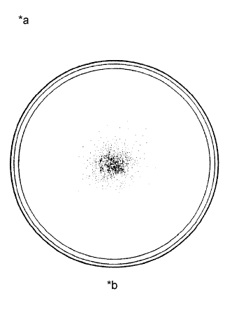
Text in Illustration *a Sample showing maximum allowable amount of powder in ATF *b Full Scale Inspect the torque converter assembly.
If any of the following problems are present, replace the torque converter assembly.
-
A metallic sound is emitted from the torque converter assembly during the stall test or when the shift lever is moved to N.
-
The one-way clutch turns smoothly or turns with difficulty in both directions.
-
The amount of powder in the ATF is more than the sample shown in the illustration (refer to the sample).
Malfunction:
Tech Tips
The sample shows approximately 0.025 liters (0.026 US qts., 0.022 Imp. qts.) of ATF in a Petri dish, which has been taken from the removed torque converter assembly.
-
-
Replace the ATF in the torque converter assembly.
Tech Tips
If the ATF is discolored or has a foul odor, stir the ATF in the torque converter assembly and drain it before replacing the ATF.
-
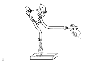
Clean and check the oil cooler and oil pipe line.
Tech Tips
-
If the torque converter assembly is inspected or the ATF is replaced, it is necessary to clean the oil cooler and oil pipe line.
-
Apply compressed air of 196 kPa (2.0 kgf/ cm2, 28 psi) into the inlet hose.
-
If a large amount of powder is found in the ATF, add new ATF using a bucket pump and clean the oil cooler and oil pipe line again.
-
If the ATF is cloudy, inspect the oil cooler.
-
-
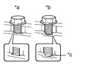
Text in Illustration *a Correct *b Incorrect *c Bottom is damaged Prevent deformation of the torque converter assembly and damage to the oil pump gear.
Note
Make sure that all of the bolts are the same length and that the specified bolts are used.
Tech Tips
If there is any damage to the tip of a bolt for the torque converter assembly or to the bottom of a bolt hole, replace the bolt and torque converter assembly.
-
-
INSTALL TORQUE CONVERTER ASSEMBLY
-
Engage the splines of the input shaft and turbine runner.
-
Engage the splines of the stator shaft and the stator while turning the torque converter assembly.
Tech Tips
If the stator shaft splines are difficult to engage with the stator splines, move the torque converter assembly back approximately 10 mm and engage the splines while rotating the torque converter assembly.
-
Turn the torque converter assembly to insert the key of the oil pump drive gear into the groove of the torque converter assembly.
-
Clean the torque converter assembly set bolt holes.
-

Text in Illustration *a Engine Surface *b Drive Plate Surface Using a vernier caliper and straightedge, measure dimension A between the transaxle contact surface of the engine and the torque converter assembly contact surface of the drive plate.
Note
Make sure to deduct the thickness of the straightedge.
-
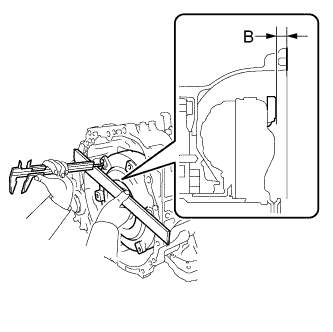
Using a vernier caliper and straightedge, measure dimension B shown in the illustration and check that dimension B is more than dimension A, which was measured in the previous step.
Standard A + 1 mm (0.0394 in.) or more Note
-
Make sure to deduct the thickness of the straightedge.
-
If the automatic transaxle assembly is installed to the engine with the torque converter assembly not sufficiently inserted, the torque converter assembly may be damaged.
-
Do not include the thickness of the set block.
-
-
-
INSTALL TRANSMISSION CASE PLUG ASSEMBLY
-
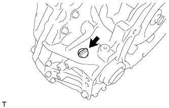
Coat a new O-ring with ATF and install it to the transmission case plug assembly.
-
Install the transmission case plug assembly to the transaxle housing.
-
-
INSTALL WIRE HARNESS CLAMP BRACKET
-
Install the 4 wire harness clamp brackets to the automatic transaxle assembly with the 4 bolts.
- Torque:
- 8.0 N*m { 82 kgf*cm, 71 in.*lbf }
-
-
INSTALL NO. 1 TRANSMISSION CONTROL CABLE BRACKET
-
Install the No. 1 transmission control cable bracket to the automatic transaxle assembly with the 2 bolts.
- Torque:
- 12 N*m { 122 kgf*cm, 9 ft.*lbf }
-
-
INSTALL FRONT ENGINE MOUNTING BRACKET
-
Install the front engine mounting bracket to the automatic transaxle assembly with the 3 bolts.
- Torque:
- 64 N*m { 653 kgf*cm, 47 ft.*lbf }
-
-
INSTALL TRANSMISSION OIL COOLER
-
Install the transmission oil cooler to the front engine mounting bracket with the 3 bolts.
- Torque:
- 14 N*m { 138 kgf*cm, 10 ft.*lbf }
-
Install the No. 1 oil cooler inlet hose and No. 1 oil cooler outlet hose to the transmission oil cooler and automatic transaxle assembly and engage the 4 clamps.
-
-
INSTALL AUTOMATIC TRANSAXLE ASSEMBLY
-
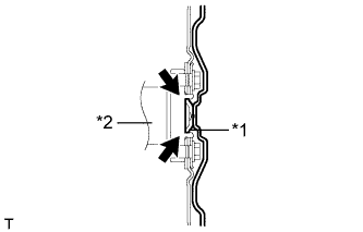
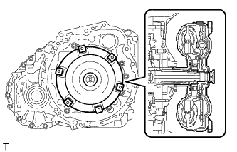
Text in Illustration *1 Torque Converter Assembly Centerpiece *2 Crankshaft Apply clutch spline grease to the round of the crankshaft that contacts the torque converter assembly centerpiece.
Clutch spline grease Toyota Genuine Clutch Spline Grease or equivalent Maximum spread About 1 g (0.0353 oz.) -
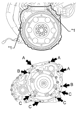
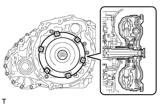
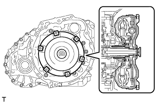
Text in Illustration *1 Knock Pin While keeping the engine and automatic transaxle assembly horizontal, align the knock pins with the holes in the automatic transaxle assembly and install the 9 bolts shown in the illustration.
Bolt Bolt Length Torque A 55 mm (2.17 in.) 64 N*m (653 kgf*cm, 47 ft.*lbf) B 50 mm (1.97 in.) 46 N*m (469 kgf*cm, 34 ft.*lbf) C 32 mm (1.26 in.) 44 N*m (449 kgf*cm, 32 ft.*lbf) 33 mm (1.30 in.) 43 N*m (438 kgf*cm, 32 ft.*lbf) Note
-
Confirm that the 2 knock pins are installed to the transaxle contact surface of the engine cylinder block before installing the automatic transaxle assembly.
-
Do not forcibly pry on the automatic transaxle assembly.
-
Check that the torque converter assembly rotates.
-
-
-
INSTALL WIRE HARNESS
-
Connect the 7 wire harness clamps and park/neutral position switch assembly connector.
-
Install the ground cable with the bolt.
- Torque:
- 12 N*m { 122 kgf*cm, 9 ft.*lbf }
-
-
INSTALL WIRING HARNESS CONNECTOR
-
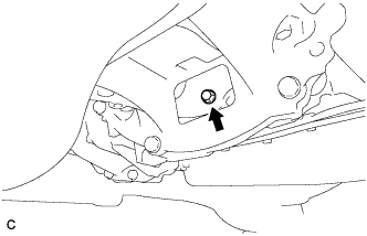
Install the wiring harness connector to the automatic transaxle assembly.
-
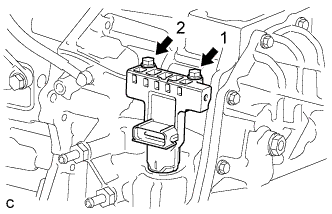
Install and tighten the 2 bolts in the order shown in the illustration.
- Torque:
- 11 N*m { 115 kgf*cm, 8 ft.*lbf }
-
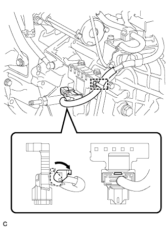
Connect the connector to the wiring harness connector.
-
Turn the lock lever and secure the connector with the lock lever.
-
Connect the wire harness clamp to the wiring harness connector.
-
-
INSTALL FRONT FRAME ASSEMBLY
-
Install the engine mounting insulator LH with the nut.
- Torque:
- 95 N*m { 969 kgf*cm, 70 ft.*lbf }
-
Install the engine mounting insulator RH with the nut.
- Torque:
- 95 N*m { 969 kgf*cm, 70 ft.*lbf }
-
Install the front engine mounting insulator with the bolt.
- Torque:
- 87 N*m { 887 kgf*cm, 64 ft.*lbf }
-
Fully tighten the 9 temporarily installed nuts of the engine mounting insulators to the specified torque.
Text in Illustration *1 Front Engine Mounting Insulator *2 Engine Mounting Insulator RH *3 Engine Mounting Insulator LH - - Tech Tips
Perform this procedure only when replacement of the engine mounting insulator is necessary.
- Torque:
- A
- 52 N*m { 530 kgf*cm, 38 ft.*lbf }
- B
- 87 N*m { 887 kgf*cm, 64 ft.*lbf }
-
Install the 4 hole plugs.
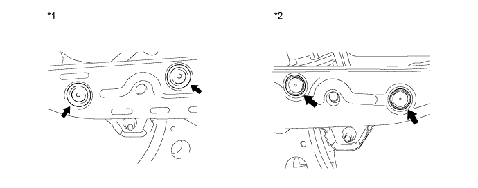
Text in Illustration *1 Engine Mounting Insulator RH *2 Engine Mounting Insulator LH Tech Tips
Perform this procedure only when replacement of the engine mounting insulator is necessary.
-
-
INSTALL ENGINE ASSEMBLY WITH TRANSAXLE
-
Set the engine assembly with transaxle on an engine lifter.
Note
-
Install height adjustment attachments and plate lift attachments under the engine assembly with transaxle.
-
To prevent the oil pan sub-assembly from deforming, do not place any attachments under the oil pan sub-assembly of the engine assembly with transaxle.
-
Make sure to support the engine assembly with transaxle securely to prevent it from falling.
-
-
Remove the engine hangers Click here.
-
Install the engine assembly with transaxle to the vehicle.
Note
Do not raise the engine assembly more than necessary. If the engine assembly is raised excessively, the vehicle may also be lifted up.
Tech Tips
-
Make sure that the engine assembly is clear of all wiring and hoses.
-
While raising the engine assembly with transaxle into the vehicle, do not allow it to contact the vehicle.
-
-
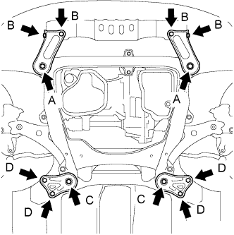
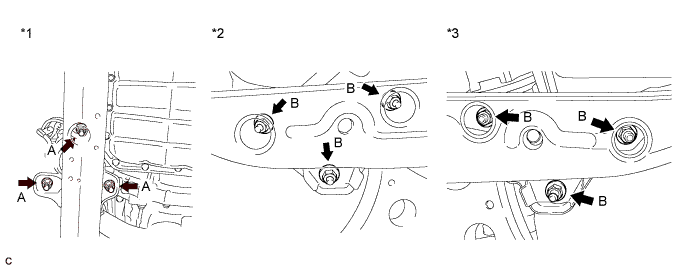
Install the frame side rail plate RH and frame side rail plate LH with the 4 bolts and 2 nuts.
- Torque:
- A
- 85 N*m { 867 kgf*cm, 63 ft.*lbf }
- B
- 64 N*m { 653 kgf*cm, 47 ft.*lbf }
-
Install the front suspension member brace rear RH and front suspension member brace rear LH with the 4 bolts and 2 nuts.
- Torque:
- C
- 85 N*m { 867 kgf*cm, 63 ft.*lbf }
- D
- 64 N*m { 653 kgf*cm, 47 ft.*lbf }
Tech Tips
Perform "Inspection After Repair" after replacing the engine assembly Click here.
-
-
INSTALL DRIVE PLATE AND TORQUE CONVERTER ASSEMBLY SETTING BOLT
-
Text in Illustration *1 Adhesive Apply a few drops of adhesive to 2 or 3 threads at the tip of each of the 6 drive plate and torque converter assembly setting bolts.
Adhesive Toyota Genuine Adhesive 1324, Three Bond 1324 or equivalent -
Turn the crankshaft to gain access to the installation locations of the 6 drive plate and torque converter assembly setting bolts and install each bolt while holding the crankshaft pulley bolt with a wrench.
- Torque:
- 41 N*m { 418 kgf*cm, 30 ft.*lbf }
Note
Install the black colored bolt first, and then the 5 silver colored bolts.
-
-
INSTALL FLYWHEEL HOUSING UNDER COVER
-
CHECK AUTOMATIC TRANSAXLE SYSTEM
Note
If automatic transaxle parts have been replaced, refer to Parts Replacement Compensation Table to determine if any additional operations are necessary Click here.