AUTOMATIC TRANSAXLE ASSEMBLY REMOVAL

Note
If automatic transaxle parts are replaced, refer to Parts Replacement Compensation Table to determine if any additional operations are necessary Click here.
-
REMOVE FLYWHEEL HOUSING UNDER COVER
-
REMOVE DRIVE PLATE AND TORQUE CONVERTER ASSEMBLY SETTING BOLT
-
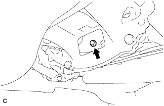
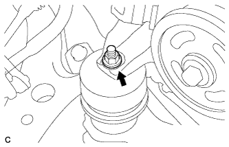
Turn the crankshaft to gain access to the removal locations of the 6 drive plate and torque converter assembly setting bolts and remove each bolt while holding the crankshaft pulley bolt with a wrench.
-
-
REMOVE ENGINE ASSEMBLY WITH TRANSAXLE
-

Place height adjustment attachments and plate lift attachments in the positions shown in the illustration and set an engine lifter underneath the engine assembly with transaxle.
Text in Illustration 
Attachment Installation Position Note
-
Install height adjustment attachments and plate lift attachments under the engine assembly with transaxle.
-
Securely support the engine assembly to prevent it from turning upside down until it is secured to an engine stand.
-
To prevent the oil pan sub-assembly from deforming, do not place any attachments under the oil pan sub-assembly of the engine assembly with transaxle.
-
Do not perform any procedures while the engine assembly is suspended because doing so may cause the engine assembly to drop, resulting in injury. However, the engine assembly needs to be suspended when it is installed or removed from an engine stand.
-
-
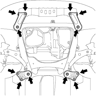
Remove the 4 bolts, 2 nuts and frame side rail plate RH and frame side rail plate LH.
-
Remove the 4 bolts, 2 nuts and front suspension member brace rear RH and front suspension member brace rear LH.
-
Operate the engine lifter and remove the engine assembly with transaxle from the vehicle.
Note
-
Make sure that the engine assembly is clear of all wiring and hoses.
-
While lowering the engine assembly from the vehicle, do not allow it to contact the vehicle.
-
-
Install the engine hangers Click here.
-
Using an engine sling device and engine lift, secure the engine assembly.
-
-
REMOVE FRONT FRAME ASSEMBLY
-
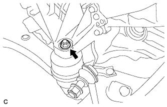
Remove the nut and separate the engine mounting insulator LH.
-
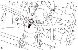
Remove the bolt and separate the front engine mounting insulator.
-
Remove the nut and separate the engine mounting insulator RH.
-
Remove the front frame assembly.
-
Using height adjustment attachments and plate lift attachments, place the engine assembly on a flat level surface.
Note
-
Using height adjustment attachments and plate lift attachments, place the engine assembly with transaxle horizontally.
-
To prevent the oil pan sub-assembly from deforming, do not place any attachments under the oil pan sub-assembly of the engine assembly with transaxle.
-
Using an engine sling device and engine lift, secure the engine assembly before service.
-
-
-
REMOVE WIRING HARNESS CONNECTOR
-
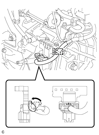
Disconnect the wire harness clamp from the wiring harness connector.
-
Turn the lock lever and disconnect the connector from the wiring harness connector.
-
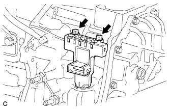
Remove the 2 bolts and wiring harness connector from the automatic transaxle assembly.
-
-
SEPARATE WIRE HARNESS
-
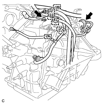
Remove the bolt and ground cable.
-
Separate the park/neutral position switch assembly connector and 7 wire harness clamps.
-
-
REMOVE AUTOMATIC TRANSAXLE ASSEMBLY
-
Using the transmission jack attachment, set the automatic transaxle assembly on a transmission jack.
Note
-
Secure the automatic transaxle assembly to the transmission jack using a suitable adapter, such as a rope or attachment.
-
To prevent the oil pan from deforming, do not place any attachments onto the oil pan of the automatic transaxle assembly.
-
Hold the engine assembly with a suitable adapter, such as a rope, during the operation.
-
-
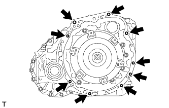
Remove the 9 bolts and automatic transaxle assembly.
Note
To prevent damage to the knock pins, do not pry between the automatic transaxle assembly and engine.
-
-
REMOVE TRANSMISSION OIL COOLER
-
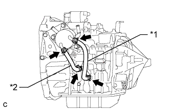
Text in Illustration *1 No. 1 Oil Cooler Inlet Hose *2 No. 1 Oil Cooler Outlet Hose Release the 4 clamps and remove the No. 1 oil cooler inlet hose and No. 1 oil cooler outlet hose from the transmission oil cooler and automatic transaxle assembly.
-
Remove the 3 bolts and transmission oil cooler from the front engine mounting bracket.
-
-
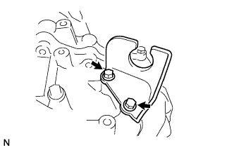
REMOVE FRONT ENGINE MOUNTING BRACKET
-
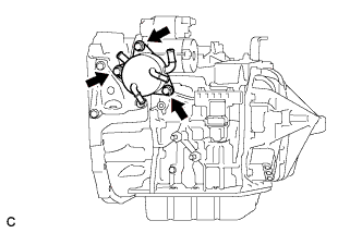
Remove the 3 bolts and front engine mounting bracket from the automatic transaxle assembly.
-
-
REMOVE NO. 1 TRANSMISSION CONTROL CABLE BRACKET
-
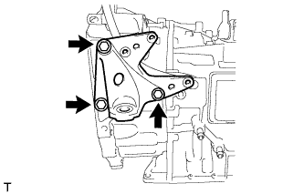
Remove the 2 bolts and No. 1 transmission control cable bracket from the automatic transaxle assembly.
-
-
REMOVE WIRE HARNESS CLAMP BRACKET
-
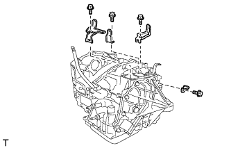
Remove the 4 bolts and 4 wire harness clamp brackets from the automatic transaxle assembly.
-
-
REMOVE TRANSMISSION CASE PLUG ASSEMBLY
-
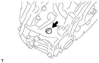
Remove the transmission case plug assembly from the transaxle housing.
-
Remove the O-ring from the transmission case plug assembly.
-
-
REMOVE TORQUE CONVERTER ASSEMBLY
-
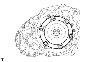
Remove the torque converter assembly from the automatic transaxle assembly.
-