AUTOMATIC TRANSAXLE SYSTEM, Diagnostic DTC:P2716

| DTC Code | DTC Name |
|---|---|
| P2716 | Pressure Control Solenoid "D" Electrical (Shift Solenoid Valve SLT) |
DESCRIPTION
Refer to the system description for DTC P2714 Click here.
| DTC No. | DTC Detection Condition | Trouble Area |
|---|---|---|
| P2716 | Open or short is detected in shift solenoid valve SLT circuit for 1 second or more while driving (1-trip detection logic). |
|
MONITOR DESCRIPTION
When an open or short in the shift solenoid valve (SLT) circuit is detected, the ECM interprets this as a fault. The ECM will turn on the MIL and store the DTC.
WIRING DIAGRAM
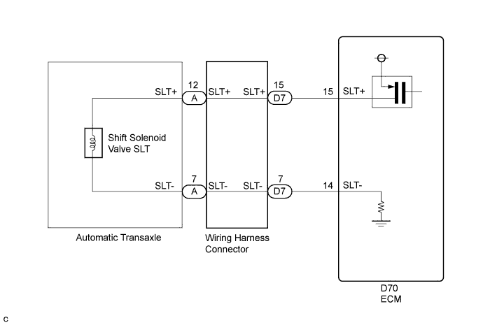
INSPECTION PROCEDURE
PROCEDURE
-
CHECK HARNESS AND CONNECTOR (SHIFT SOLENOID VALVE SLT CIRCUIT)
-
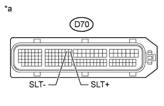
Text in Illustration *a Front view of wire harness connector
(to ECM)
Disconnect the D70 ECM connector.
-
Measure the resistance according to the value(s) in the table below.
Standard Resistance Tester Connection Condition Specified Condition D70-15 (SLT+) - D70-14 (SLT-) 20°C (68°F) 5.0 to 5.6 Ω D70-15 (SLT+) - Body ground and other terminals Always 10 kΩ or higher D70-14 (SLT-) - Body ground and other terminals Always 10 kΩ or higher
NG 
CHECK HARNESS AND CONNECTOR (ECM - WIRING HARNESS CONNECTOR) Click here
OK 
REPLACE ECM Click here
-
-
CHECK HARNESS AND CONNECTOR (ECM - WIRING HARNESS CONNECTOR)
-
Disconnect the connector from the wiring harness connector.
-
Measure the resistance according to the value(s) in the table below.
Standard Resistance Tester Connection Condition Specified Condition D70-15 (SLT+) - D7-15 (SLT+) Always Below 1 Ω D70-14 (SLT-) - D7-7 (SLT-) Always Below 1 Ω D70-15 (SLT+) or D7-15 (SLT+) - Body ground and other terminals Always 10 kΩ or higher D70-14 (SLT-) or D7-7 (SLT-) - Body ground and other terminals Always 10 kΩ or higher
NG 
REPAIR OR REPLACE HARNESS OR CONNECTOR
OK 
-
-
INSPECT TRANSMISSION WIRE (SLT)
-
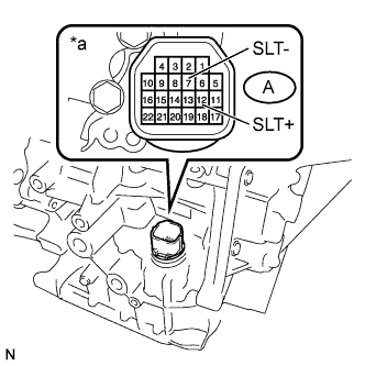
Text in Illustration *a Component without harness connected
(Transmission Wire)
Remove the wiring harness connector from the transaxle.
-
Measure the resistance according to the value(s) in the table below.
Standard Resistance Tester Connection Condition Specified Condition A-12 (SLT+) - A-7 (SLT-) 20°C (68°F) 5.0 to 5.6 Ω A-12 (SLT+) - Body ground and other terminals Always 10 kΩ or higher A-7 (SLT-) - Body ground and other terminals Always 10 kΩ or higher
NG
INSPECT SHIFT SOLENOID VALVE SLT Click here
OK
REPLACE WIRING HARNESS CONNECTOR Click here
-
-
INSPECT SHIFT SOLENOID VALVE SLT
-
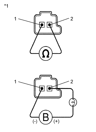
Text in Illustration *1 Shift Solenoid Valve SLT Remove shift solenoid valve SLT.
-
Measure the resistance according to the value(s) in the table below.
Standard Resistance Tester Connection Condition Specified Condition 1 - 2 20°C (68°F) 5.0 to 5.6 Ω -
Connect a battery positive (+) lead with a 21 W bulb to terminal 2 and a negative (-) lead to terminal 1 of the solenoid valve connector. Then check that the valve moves and makes an operating sound.
OK Valve moves and makes an operating sound.
NG
REPLACE SHIFT SOLENOID VALVE SLT Click here
OK
REPLACE TRANSMISSION WIRE Click here
-