AUTOMATIC TRANSAXLE ASSEMBLY INSTALLATION

-
INSTALL TORQUE CONVERTER ASSEMBLY
-
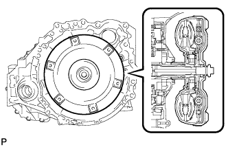
Engage the splines of the input shaft and turbine runner.
-
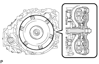
Engage the splines of the stator shaft and the stator while turning the torque converter assembly.
Tech Tips
If the stator shaft splines are difficult to engage with the stator splines, move the torque converter assembly back approximately 10 mm (0.393 in.) and engage the splines while rotating the torque converter assembly.
-
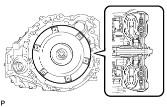
Turn the torque converter assembly to insert the key of the oil pump drive gear into the groove of the torque converter assembly.
-
Clean the torque converter assembly set bolt holes.
-
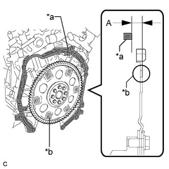
Text in Illustration *a Engine Surface *b Drive Plate Surface Using a vernier caliper and straightedge, measure dimension A between the transaxle contact surface of the engine and the torque converter assembly contact surface of the drive plate.
Note
Make sure to deduct the thickness of the straightedge.
-
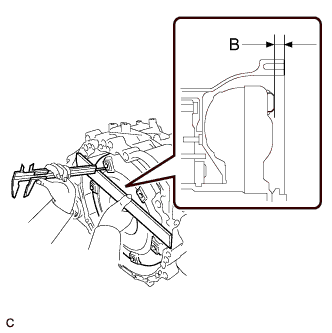
Using a vernier caliper and straightedge, measure dimension B shown in the illustration and check that dimension B is more than dimension A, which was measured in the previous step.
Standard A + 1 mm (0.0394 in.) or more Note
-
Make sure to deduct the thickness of the straightedge.
-
If the automatic transaxle assembly is installed to the engine with the torque converter assembly not sufficiently inserted, the torque converter assembly may be damaged.
-
-
-
INSTALL SPEEDOMETER DRIVEN HOLE (ATM) COVER SUB-ASSEMBLY
-
Apply ATF to a new O-ring and install it to the speedometer driven hole (ATM) cover sub-assembly.
-
Install the speedometer driven hole (ATM) cover sub-assembly to the automatic transaxle assembly with the bolt.
- Torque:
- 5.5 N*m { 56 kgf*cm, 49 in.*lbf }
-
-
INSTALL NO. 1 TRANSMISSION CONTROL CABLE BRACKET
-
Install the No. 1 transmission control cable bracket to the automatic transaxle assembly with the 2 bolts.
- Torque:
- 12 N*m { 122 kgf*cm, 9 ft.*lbf }
-
-
INSTALL WIRE HARNESS CLAMP BRACKET
-
Install the 5 wire harness clamp brackets to the automatic transaxle assembly with the 5 bolts.
- Torque:
- 8.0 N*m { 82 kgf*cm, 71 in.*lbf }
-
-
INSTALL FRONT ENGINE MOUNTING BRACKET
-
Install the front engine mounting bracket to the automatic transaxle assembly with the 3 bolts.
- Torque:
- 64 N*m { 653 kgf*cm, 47 ft.*lbf }
-
-
INSTALL AUTOMATIC TRANSAXLE ASSEMBLY
-
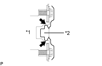
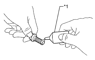
Text in Illustration *1 Crankshaft *2 Torque Converter Assembly Centerpiece Apply clutch spline grease to the surface of the crankshaft that contacts the torque converter assembly centerpiece.
Clutch spline grease Toyota Genuine Clutch Spline Grease or equivalent Maximum spread About 1 g (0.0353 oz.) -
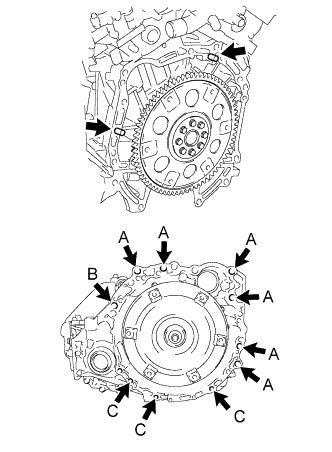
While keeping the engine and automatic transaxle assembly horizontal, align the knock pins with the holes in the automatic transaxle assembly and install the 10 bolts shown in the illustration.
- Torque:
- Bolt A
- 64 N*m { 653 kgf*cm, 47 ft.*lbf }
- Bolt B
- 64 N*m { 653 kgf*cm, 47 ft.*lbf }
- Bolt C
- 43 N*m { 438 kgf*cm, 32 ft.*lbf }
Note
-
Confirm that the 2 knock pins are installed to the automatic transaxle assembly contact surface of the engine cylinder block before installing the automatic transaxle assembly.
-
Do not forcibly pry on the automatic transaxle assembly.
-
Check that the torque converter assembly rotates.
Bolt length Bolt A 55 mm (2.17 in.) Bolt B 50 mm (1.97 in.) Bolt C 33 mm (1.30 in.) -
Clean and degrease the bolt and the installation hole in the automatic transaxle assembly.
-
Apply a few drops of adhesive to 2 or 3 threads at the tip of each bolt.
Adhesive Toyota Genuine Adhesive 1344, Three Bond 1344 or equivalent -
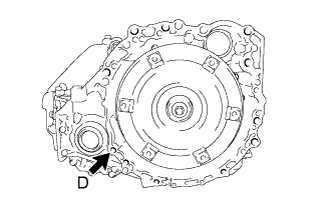
Install the bolt.
- Torque:
- Bolt D
- 46 N*m { 469 kgf*cm, 34 ft.*lbf }
Bolt length Bolt D 41 mm (1.61 in.) -
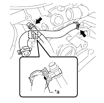
Text in Illustration *a Paint Install the No. 4 water by-pass hose to the water inlet pipe and engage the clamp. (w/ ATF Warmer)
Note
-
Install the clamp so that the neck of the clamp is aligned with the paint.
-
Ensure that the paint is completely covered by the clamp.
-
-
Install the clamp and connect the breather plug. (w/ ATF Warmer)
-
-
INSTALL WIRE HARNESS
-
Connect the 7 clamps and connector.
-
Install the wire harnesses with the bolt.
- Torque:
- 12 N*m { 122 kgf*cm, 9 ft.*lbf }
-
-
INSTALL TCM
-
Temporarily install the TCM to the automatic transaxle assembly with the 2 bolts.
-
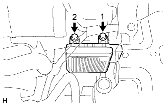
Tighten the 2 bolts in the order shown in the illustration.
- Torque:
- 11 N*m { 115 kgf*cm, 8 ft.*lbf }
-
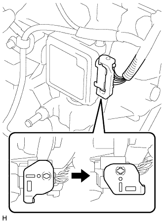
Connect the connector to the TCM.
-
Turn the lock lever and secure the connector with the lock lever.
-
-
INSTALL FRONT FRAME ASSEMBLY
-
Install the engine mounting insulator RH with the nut.
- Torque:
- 95 N*m { 969 kgf*cm, 70 ft.*lbf }
-
Install the engine mounting insulator LH with the nut.
- Torque:
- 95 N*m { 969 kgf*cm, 70 ft.*lbf }
-
Install the front engine mounting insulator assembly with the bolt.
- Torque:
- 87 N*m { 887 kgf*cm, 64 ft.*lbf }
-
Connect the 2 wire clamps and vacuum switching valve connector.
-
Connect the 2 wire clamps.
-
Fully tighten the 9 temporarily installed nuts of the front engine mounting insulator assembly, engine mounting insulator LH and engine mounting insulator RH to the specified torque.
Tech Tips
Perform this procedure only when replacement of the engine mounting insulator is necessary.
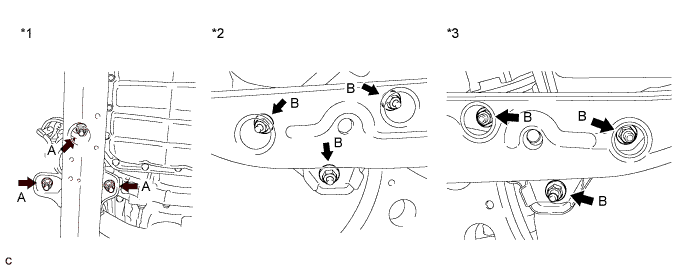
Text in Illustration *1 Front Engine Mounting Insulator Assembly Side *2 Engine Mounting Insulator RH Side *3 Engine Mounting Insulator LH Side - - - Torque:
- A
- 52 N*m { 530 kgf*cm, 38 ft.*lbf }
- Torque:
- B
- 87 N*m { 887 kgf*cm, 64 ft.*lbf }
-
Install the 4 hole plugs.
Tech Tips
Perform this procedure only when replacement of the engine mounting insulator is necessary.
Text in Illustration *1 Engine Mounting Insulator RH Side *2 Engine Mounting Insulator LH Side
-
-
INSTALL OIL COOLER HOSE (w/ ATF Warmer)
-
Install the No. 1 oil cooler inlet hose and No. 1 oil cooler outlet hose to the automatic transaxle assembly and engage the 2 clamps.
-
-
INSTALL TRANSMISSION OIL THERMOSTAT (w/ Transmission Oil Thermostat)
-
w/ Transmission Oil Thermostat:
-
Connect the clamp and install the transmission oil thermostat with the bolt.
- Torque:
- 20 N*m { 199 kgf*cm, 14 ft.*lbf }
-
Connect the inlet oil cooler hose to the transmission oil thermostat and slide the clip to secure it.
-
Connect the outlet oil cooler hose to the transmission oil thermostat and slide the clip to secure it.
-
-
-
INSTALL TRANSMISSION OIL COOLER (w/ ATF Warmer)
-
Install the transmission oil cooler and transmission oil cooler stay to the front engine mounting bracket with the 3 bolts.
- Torque:
- 14 N*m { 138 kgf*cm, 10 ft.*lbf }
-
w/o Transmission Oil Thermostat:
-
Connect the No. 3 water by-pass hose, No. 4 water by-pass hose, No. 1 oil cooler outlet hose and No. 1 oil cooler inlet hose to the transmission oil cooler and engage the 4 clamps.
-
-
w/ Transmission Oil Thermostat:
-
Connect the No. 3 water by-pass hose, No. 4 water by-pass hose, No. 1 transmission oil cooler hose assembly and No. 1 oil cooler inlet hose to the transmission oil cooler and engage the 4 clamps.
-
-
-
INSTALL ENGINE ASSEMBLY WITH TRANSAXLE
-
Set the engine assembly with transaxle on the engine lifter.
Note
-
Place the height adjustment and plate lift attachments under the engine assembly with transaxle.
-
Servicing an engine assembly with transaxle while it is hanging is dangerous. This can be done only when installing/removing the engine assembly with transaxle to/from an engine stand.
-
To prevent the oil pan from deforming, do not place any attachments under the oil pan of the engine assembly with transaxle.
-
Make sure to support the engine assembly with transaxle securely to prevent it from falling.
-
-
Remove the No. 1 engine hanger and No. 2 engine hanger Click here.
-
Install the engine assembly with transaxle to the vehicle.
Note
-
Do not raise the engine assembly with transaxle more than necessary. If the engine assembly with transaxle is raised excessively, the vehicle may also be lifted up.
-
Make sure that the engine assembly with transaxle is clear of all wiring and hoses.
-
While raising the engine assembly with transaxle into the vehicle, do not allow it to contact the vehicle.
-
-
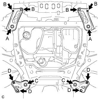
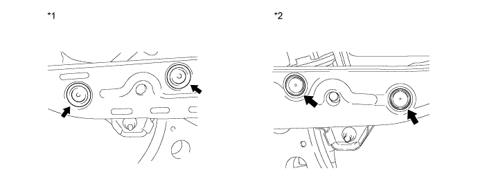
Install the frame side rail plate RH and frame side rail plate LH with the 4 bolts and 2 nuts.
- Torque:
- A
- 85 N*m { 867 kgf*cm, 63 ft.*lbf }
- B
- 64 N*m { 653 kgf*cm, 47 ft.*lbf }
-
Install the front suspension member rear brace RH and front suspension member rear brace LH with the 4 bolts and 2 nuts.
- Torque:
- C
- 85 N*m { 867 kgf*cm, 63 ft.*lbf }
- D
- 64 N*m { 653 kgf*cm, 47 ft.*lbf }
Tech Tips
Perform "Inspection After Repair" after replacing the engine assembly Click here.
-
-
INSTALL DRIVE PLATE AND TORQUE CONVERTER ASSEMBLY SETTING BOLT
-
Text in Illustration *1 Adhesive 1324 Apply a few drops of adhesive to 2 or 3 threads at the tip of each of the 6 drive plate and torque converter assembly setting bolts.
Adhesive Toyota Genuine Adhesive 1324, Three Bond 1324 or equivalent. -
Turn the crankshaft to gain access to the installation locations of the 6 drive plate and torque converter assembly setting bolts and install each bolt while holding the crankshaft pulley bolt with a wrench.
- Torque:
- 41 N*m { 418 kgf*cm, 30 ft.*lbf }
Note
First install the black colored bolt, and then the remaining 5 silver colored bolts.
-
-
INSTALL NO. 1 EXHAUST PIPE SUPPORT BRACKET SUB-ASSEMBLY
-
CHECK AUTOMATIC TRANSAXLE SYSTEM
Note
If automatic transaxle parts have been replaced, refer to Parts Replacement Compensation Table to determine if any additional operations are necessary Click here.