AUTOMATIC TRANSAXLE ASSEMBLY REMOVAL

Note
If automatic transaxle parts are replaced, refer to Parts Replacement Compensation Table to determine if any additional operations are necessary Click here.
-
INSTALL NO. 1 EXHAUST PIPE SUPPORT BRACKET SUB-ASSEMBLY
-
REMOVE DRIVE PLATE AND TORQUE CONVERTER ASSEMBLY SETTING BOLT
-
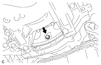
Turn the crankshaft to gain access to the 6 drive plate and torque converter assembly setting bolts and each bolt while holding the crankshaft pulley bolt with a wrench.
Tech Tips
There will be one black colored bolt.
-
-
REMOVE ENGINE ASSEMBLY WITH TRANSAXLE
-
Set the engine lifter.
Text in Illustration 
Attachment Installation Position Note
-
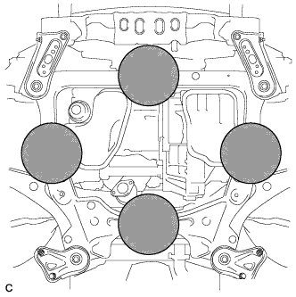
Place the height adjustment and plate lift attachments under the engine assembly with transaxle.
-
Securely support the engine assembly to prevent it from turning upside down until it is secured to an engine stand.
-
To prevent the oil pan from deforming, do not place any attachments under the oil pan of the engine assembly with transaxle.
-
Do not perform any procedure while the engine assembly is suspended because doing so may cause the engine assembly to drop, resulting in injury. However, the engine assembly needs to be suspended when it is installed to or removed from an engine stand.
-
-
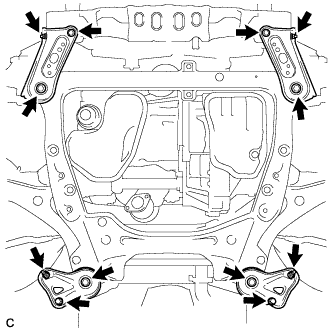
Remove the 4 bolts, 2 nuts and frame side rail plates RH and LH.
-
Remove the 4 bolts, 2 nuts and front suspension member rear braces RH and LH.
-
Operate the engine lifter, then remove the engine assembly with transaxle from the vehicle.
Note
-
Make sure that the engine assembly with transaxle is clear of all wiring and hoses.
-
While lowering the engine assembly with transaxle from the vehicle, do not allow it to contact the vehicle.
-
-
Install the engine hangers Click here.
-
-
REMOVE TRANSMISSION OIL COOLER (w/ ATF Warmer)
-
w/o Transmission Oil Thermostat:
-
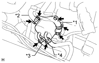
Text in Illustration *1 No. 3 Water By-pass Hose *2 No. 4 Water By-pass Hose *3 No. 1 Oil Cooler Outlet Hose *4 No. 1 Oil Cooler Inlet Hose Release the 4 clamps and disconnect the No. 3 water by-pass hose, No. 4 water by-pass hose, No. 1 oil cooler outlet hose and No. 1 oil cooler inlet hose from the transmission oil cooler.
-
-
w/ Transmission Oil Thermostat:
-
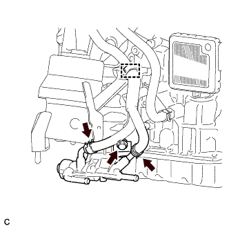
Text in Illustration *1 No. 3 Water By-pass Hose *2 No. 4 Water By-pass Hose *3 No. 1 Transmission Oil Cooler Hose Assembly *4 No. 1 Oil Cooler Inlet Hose Release the 4 clamps and disconnect the No. 3 water by-pass hose, No. 4 water by-pass hose, No. 1 transmission oil cooler hose assembly and No. 1 oil cooler inlet hose from the transmission oil cooler.
-
-
Remove the 3 bolts, transmission oil cooler and transmission oil cooler stay from the front engine mounting bracket.
-
-
REMOVE TRANSMISSION OIL THERMOSTAT (w/ Transmission Oil Thermostat)
-
w/ Transmission Oil Thermostat:
-
Disconnect the inlet oil cooler hose and outlet oil cooler hose.
-
Disconnect the clamp and remove the bolt and transmission oil thermostat.
-
-
-
REMOVE OIL COOLER HOSE (w/ ATF Warmer)
-
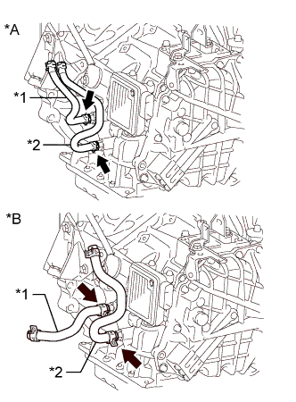
Text in Illustration *A w/o Transmission Oil Thermostat *B w/ Transmission Oil Thermostat *1 No. 1 Oil Cooler Outlet Hose *2 No. 1 Oil Cooler Inlet Hose Release the 2 clamps and remove the No. 1 oil cooler inlet hose and No. 1 oil cooler outlet hose from the automatic transaxle assembly.
-
-
REMOVE FRONT FRAME ASSEMBLY
-
Disconnect the 2 clamps.
-
Disconnect the 2 clamps and vacuum switching valve connector.
-
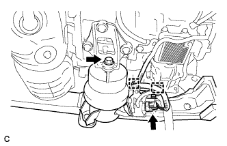
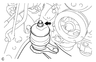
Remove the bolt and disconnect the front engine mounting insulator assembly.
-
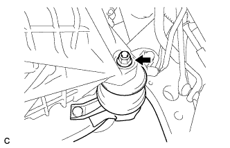
Remove the nut and disconnect the engine mounting insulator LH.
-
Remove the nut and disconnect the engine mounting insulator RH.
-
Remove the front frame assembly.
-
-
REMOVE TCM
-
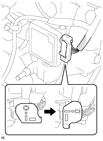
Turn the lock lever and disconnect the connector from the TCM.
-
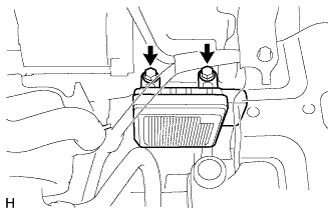
Remove the 2 bolts and TCM from the automatic transaxle assembly.
-
-
SEPARATE WIRE HARNESS
-
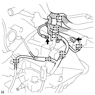
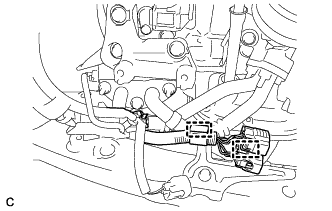
Remove the bolt and disconnect the connector and 7 clamps from the automatic transaxle assembly.
-
-
REMOVE AUTOMATIC TRANSAXLE ASSEMBLY
-
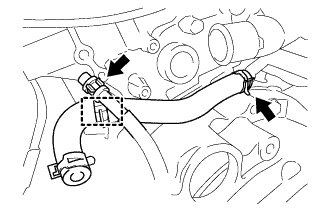
Disconnect the breather plug and remove the clamp. (w/ ATF Warmer)
-
Release the clamp and remove the No. 4 water by-pass hose from the water inlet pipe. (w/ ATF Warmer)
-
Using a transmission jack attachment, set the automatic transaxle assembly on a transmission jack.
Note
-
Secure the automatic transaxle assembly to the transmission jack using a suitable adapter, such as a rope or attachment.
-
To prevent the automatic transaxle oil pan sub-assembly from deforming, do not place any attachments onto the automatic transaxle oil pan sub-assembly of the automatic transaxle assembly.
-
Hold the engine assembly with a suitable adapter, such as a rope, during the operation.
-
-
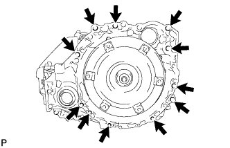
Remove the 11 bolts and automatic transaxle assembly.
Note
To prevent damage to the knock pins, do not pry between the automatic transaxle assembly and engine assembly.
-
-
REMOVE FRONT ENGINE MOUNTING BRACKET
-
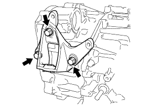
Remove the 3 bolts and front engine mounting bracket from the automatic transaxle assembly.
-
-
REMOVE WIRE HARNESS CLAMP BRACKET
-
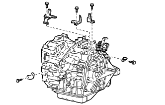
Remove the 5 bolts and 5 wire harness clamp brackets from the automatic transaxle assembly.
-
-
REMOVE NO. 1 TRANSMISSION CONTROL CABLE BRACKET
-
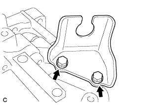
Remove the 2 bolts and No. 1 transmission control cable bracket from the automatic transaxle assembly.
-
-
REMOVE SPEEDOMETER DRIVEN HOLE (ATM) COVER SUB-ASSEMBLY
-
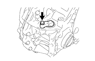
Remove the bolt and speedometer driven hole (ATM) cover sub-assembly from the automatic transaxle assembly.
-
Remove the O-ring from the speedometer driven hole (ATM) cover sub-assembly.
-
-
REMOVE TORQUE CONVERTER ASSEMBLY
-
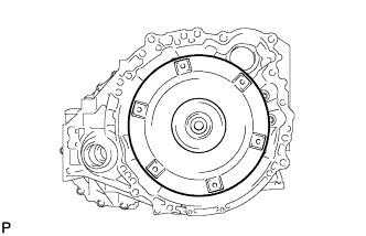
Remove the torque converter assembly from the automatic transaxle assembly.
-
-
INSPECT TORQUE CONVERTER ASSEMBLY
-
Inspect the one-way clutch.
-
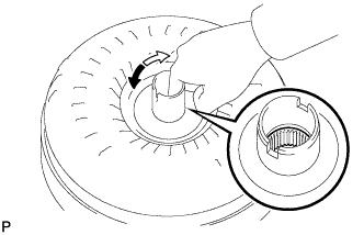
Press on the splines of the stator with a finger and rotate it. Check that it rotates smoothly when turned clockwise and rotates with difficulty when turned counterclockwise.
If necessary, clean the torque converter assembly and recheck the one-way clutch.
Replace the torque converter assembly if the one-way clutch still fails the inspection.
Text in Illustration 
Difficult 
Smooth
-
-
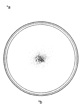
Text in Illustration *a Sample showing maximum allowable amount of powder in ATF *b Full Scale Inspect the torque converter assembly.
If any of the following problems are present, replace the torque converter assembly.
-
A metallic sound is emitted from the torque converter assembly during the stall test or when the shift lever is moved to N.
-
The one-way clutch turns smoothly or turns with difficulty in both directions.
-
The amount of powder in the ATF is more than the sample shown in the illustration (refer to the sample).
Malfunction:
Tech Tips
The sample shows approximately 0.025 liters (0.026 US qts., 0.022 Imp. qts.) of ATF in a Petri dish, which has been taken from the removed torque converter assembly.
-
-
Replace the ATF in the torque converter assembly.
Tech Tips
If the ATF is discolored or has a foul odor, stir the ATF in the torque converter assembly and drain it before replacing the ATF.
-
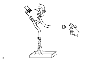
Clean and check the oil cooler and oil pipe line.
Tech Tips
-
If the torque converter assembly is inspected or the ATF is replaced, it is necessary to clean the oil cooler and oil pipe line.
-
Apply compressed air of 196 kPa (2.0 kgf/ cm2, 28 psi) into the inlet hose.
-
If a large amount of powder is found in the ATF, add new ATF using a bucket pump and clean the oil cooler and oil pipe line again.
-
If the ATF is cloudy, inspect the oil cooler.
-
-
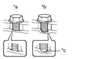
Text in Illustration *a Correct *b Incorrect *c Bottom is damaged Prevent deformation of the torque converter assembly and damage to the oil pump gear.
Note
Make sure that all of the bolts are the same length and that the specified bolts are used.
Tech Tips
If there is any damage to the tip of a bolt for the torque converter assembly or to the bottom of a bolt hole, replace the bolt and torque converter assembly.
-