AUTOMATIC TRANSAXLE SYSTEM TERMINALS OF ECM

-
ECM
Tech Tips
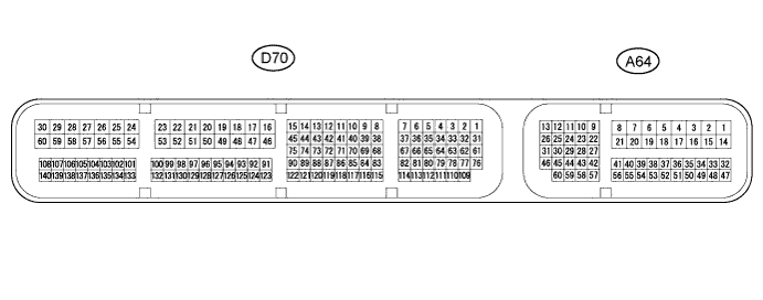
The standard voltage between each pair of ECM terminals is shown in the table below. The appropriate conditions for checking each pair of terminals are also indicated. The result of checks should be compared with the standard voltage for that pair of terminals, displayed in the "Specified Condition" column. The illustration above can be used as a reference to identify the ECM terminal locations.
Terminal No. (Symbol) Wiring Color Terminal Description Condition Specified Condition D70-3 (SL) - D70-16 (E1) R - BR Shift solenoid valve (SL) signal All gears
(Lock-up on / Flex lock-up on)
11 to 14 V D70-5 (SL1+) - D70-4 (SL1-) V - B Shift solenoid valve (SL1) signal 1st, 2nd, 3rd or 4th gear Pulse generation D70-7 (SLU+) - D70-6 (SLU-) L - G Shift solenoid valve (SLU) signal All gears
(Lock-up on / Flex lock-up on)
Pulse generation D70-9 (SL4+) - D70-8 (SL4-) V - W Shift solenoid valve (SL4) signal 3rd or 5th gear Pulse generation D70-11 (SL3+) - D70-10 (SL3-) L - P Shift solenoid valve (SL3) signal 2nd or 6th gear Pulse generation D70-13 (SL2+) - D70-12 (SL2-) LG - GR Shift solenoid valve (SL2) signal 4th, 5th or 6th gear Pulse generation D70-15 (SLT+) - D70-14 (SLT-) W - Y Shift solenoid valve (SLT) signal Engine idling Pulse generation D70-63 (NSW) - D70-16 (E1) LG - BR Park/neutral position switch assembly signal Engine switch on (IG) and shift lever in P or N Below 2 V Engine switch on (IG) and shift lever not in P or N 11 to 14 V D70-66 (R) - D70-16 (E1) GR - BR R shift position switch signal Engine switch on (IG) and shift lever in R 11 to 14 V Engine switch on (IG) and shift lever not in R Below 1 V D70-67 (D) - D70-16 (E1) G - BR D shift position switch signal Engine switch on (IG) and shift lever in D or S 11 to 14 V Engine switch on (IG) and shift lever not in D or S Below 1 V D70-70 (P) - D70-16 (E1) B - BR P shift position switch signal Engine switch on (IG) and shift lever in P 11 to 14 V Engine switch on (IG) and shift lever not in P Below 1 V D70-71 (N) - D70-16 (E1) L - BR N shift position switch signal Engine switch on (IG) and shift lever in N 11 to 14 V Engine switch on (IG) and shift lever not in N Below 1 V D70-116 (NTB) - D70-16 (E1) B - BR Power source for sensor (fixed voltage) Engine switch on (IG) 11 to 14 V D70-115 (NTO) - D70-16 (E1) R - BR Speed sensor (NT) signal Engine idle speed Pulse generation D70-118 (NCB) - D70-16 (E1) LG - BR Power source for sensor (fixed voltage) Engine switch on (IG) 11 to 14 V D70-117 (NCO) - D70-16 (E1) W - BR Speed sensor (NC) signal Vehicle driving Pulse generation D70-120 (THO1) - D70-119 (ETHO) LG - P ATF temperature sensor signal ATF temperature: 115°C (239°F) or more Below 1.5 V A64-27 (S) - D70-16 (E1) Y - BR S shift position switch signal Engine switch on (IG) and shift lever in S 11 to 14 V Engine switch on (IG) and shift lever not in S Below 1 V A64-42 (SFTU) - D70-16 (E1) R - BR Up shift switch signal Engine switch on (IG) and shift lever in S 11 to 14 V Engine switch on (IG) and shift lever in "+" (Up shift) Below 1 V A64-43 (SFTD) - D70-16 (E1) L - BR Down shift switch signal Engine switch on (IG) and shift lever in S 11 to 14 V Engine switch on (IG) and shift lever in "-" (Down shift) Below 1 V