LANE RECOGNITION CAMERA SENSOR INSTALLATION

Note
-
If the lane departure warning camera bracket is deformed or damaged, replace it together with the windshield glass.
-
If the lane departure warning camera is dropped, replace it with a new one.
-
When replacing the windshield glass of a vehicle equipped with a lane departure warning camera, make sure to use a Lexus genuine part. The lane departure warning camera may not be able to be installed due to a missing bracket or the lane departure alert system may not operate properly due to a difference in the transmissivity or black ceramic border.
-
INSTALL LANE DEPARTURE WARNING CAMERA
-
When using a new lane departure warning camera:
-
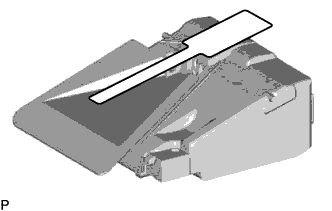
Remove the protective film.
Note
Do not touch the camera lens after removing the protective film.
-
-
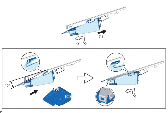
Engage the 2 guides as shown in the illustration.
Note
Do not touch the camera lens.
-
Engage the guide as shown in the illustration.
-
Connect the connector and install the lane departure warning camera.
-
-
INSTALL LANE DEPARTURE WARNING CAMERA COVER NO.1
-
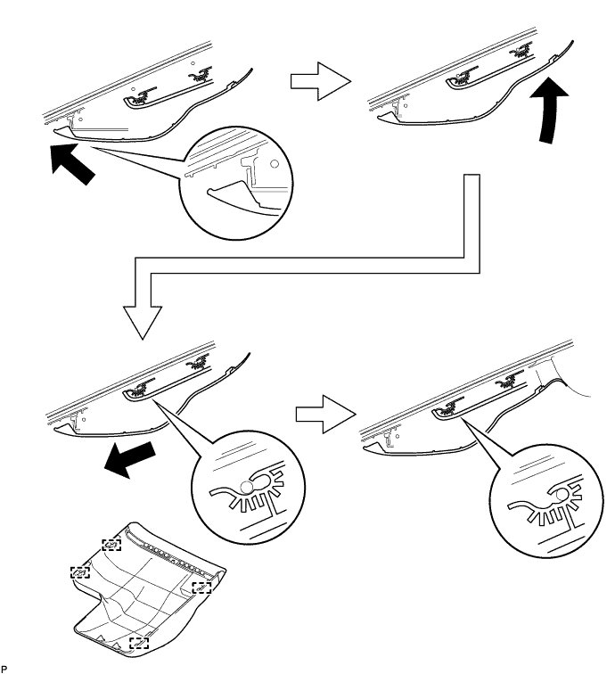
Engage the 4 guides and install the lane departure warning camera cover as shown in the illustration.
-
-
INSPECT LANE DEPARTURE WARNING CAMERA COVER NO.1
-
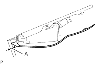
Check the clearance of area A.
Standard Clearance Area Measurement A 1.0 to 3.0 mm (0.0394 to 0.118 in.) Tech Tips
If the result is not as specified, the guides are not engaged properly. Reinstall the lane departure warning camera cover.
-
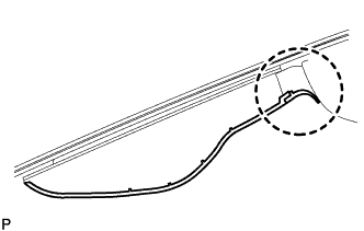
Check that the lip of the lane departure warning camera cover is as shown in the illustration.
Note
Be careful not to push in the lip of the lane departure warning camera cover as it is soft.
-
-
ADJUST LANE DEPARTURE WARNING CAMERA
Note
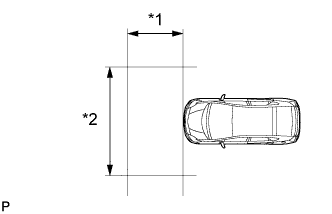
Text in Illustration *1 1.5 m or more *2 3 m or more
-
Make sure there are no black and white patterned objects in front of the vehicle.
-
Be sure to perform the measurement on a level surface that is free of obstacles and extends 1.5 m (4.92 ft.) or more in front of the vehicle.
-
Make sure that there is no wind when performing the measurement.
-
Check that there are no reflective materials in the surroundings or on the ground within a 3 m (9.84 ft.) x 3 m (9.84 ft.) area in front of the vehicle.
-
Perform the inspection in a bright area.
-
Prepare for beam axis learning.
-
Move the vehicle to a level surface.
-
Make sure the engine oil in the vehicle is at the specified level.
-
Make sure the engine coolant in the vehicle is at the specified level.
-
Make sure the fuel tank is full.
-
Make sure the spare tire is in the vehicle.
-
Make sure the standard tools are in the vehicle.
-
Make sure nobody is in the vehicle.
-
Make sure no extra loads are in the vehicle.
-
Adjust the tire pressures to the specified pressure.
-
Clean the windshield.
-
-
Perform front wheel alignment adjustment.
-
Perform front wheel alignment adjustment Click here.
Note
Perform this procedure as accurately as possible.
-
-
Perform rear wheel alignment adjustment.
-
Perform rear wheel alignment adjustment Click here.
Note
-
Perform this procedure as accurately as possible.
-
-
-
Create a target sheet.
-

Print or copy the illustration . Check that the dimensions are within +/- 5 mm (0.197 in.) of the ones in the table below.
Dimension Area Specification A 160 mm (6.30 in.) B 160 mm (6.30 in.) C 80 mm (3.15 in.) D 16 mm (0.630 in.) Note
-
Make sure that the black areas of the target sheet are not glossy.
-
Make sure that the borders of the black and white areas on the target sheet are straight, and are not warped or blurry.
If the dimensions of the print or copy are not as specified, adjust settings and reprint or recopy so that the dimensions are as specified.

-
-
-
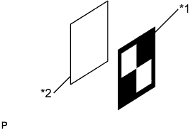
Attach the target sheet.
Text in Illustration *1 Target Sheet *2 Cardboard
-
Place the prepared target sheet on a piece of cardboard of the same size with the black area on the top right, as shown in the illustration. Then use double-sided tape to secure the target sheet in place.
Note
Do not attach reflective tape, such as transparent adhesive tape, etc. to the target face, as this may affect target recognition.
-
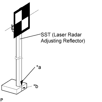
Text in Illustration *a Pointed Tip Weight *b Mark-off Line Hang a weight with a pointed tip from the center of the target sheet. Then, with double-sided tape, attach the target sheet to the reflector so that the weight aligns with the mark-off line of SST (laser radar adjusting reflector).
- SST
- 09870-60000 ( 09870-60010, 09870-60020 )
Note
-
Perform this procedure as accurately as possible.
-
Attach the target sheet so that it is horizontal with the ground.
-
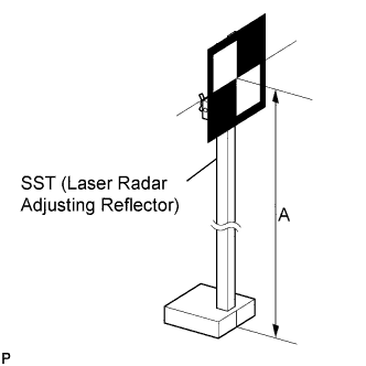
Move the reflector up and down to position the center of the target at the height shown in the illustration and secure it in place.
Dimension A 1270 mm (4.17 ft.) - SST
- 09870-60000 ( 09870-60010, 09870-60020 )
Note
Perform this procedure as accurately as possible.
-
-
Measure the target placement point.
Note
-
Do not place black and white patterned objects near the target.
-
Face the vehicle toward a wall with no patterns or make sure the background behind the target has no patterns.
-
Perform this procedure as accurately as possible.
-
Do not place reflective materials in the area behind the target.
-
Make sure the distance between the target and wall is within 3 m (9.84 ft.).
-
Make sure the shadow of the target is not on the wall as the camera may have a recognition error.
-
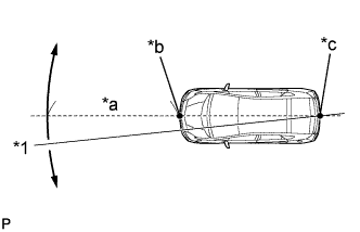
Text in Illustration *1 Line *a Approximately 2 m (6.56 ft.) *b Point A *c Point B From the center of the front and rear bumpers (center of the emblems), hang a weight with a pointed tip, and mark the front bumper center point A and the rear bumper center point B on the ground.
-
Draw a line that connects points A and B, and extend the line approximately 2 m (6.56 ft.) beyond the front of the vehicle.
Tech Tips
Secure the end of a string to point B. Then hold the other end of the string approximately 2 m (6.56 ft.) in front of the vehicle, and move it to the left or right to align the string with point A to make a straight line.
-
Mark point C (placement point 1) 1120 mm (3.67 ft.) from the front bumper center point A.
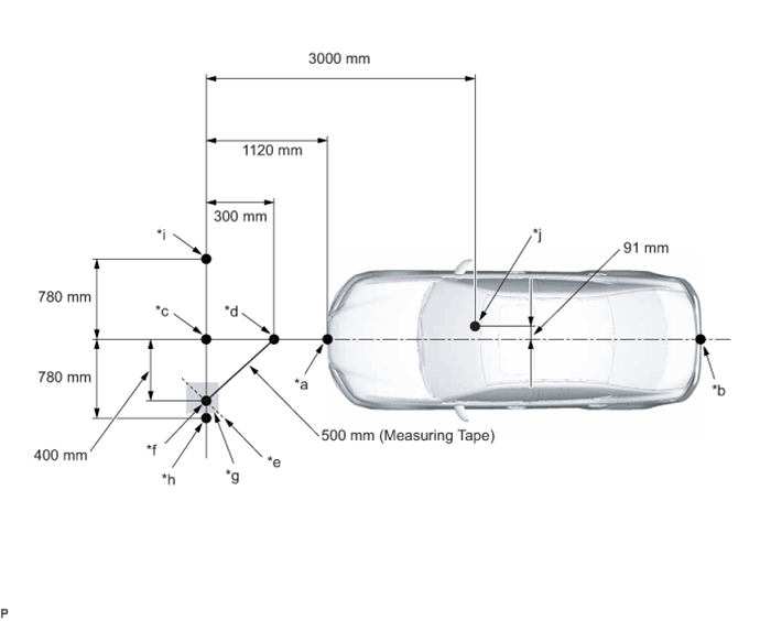
Text in Illustration *a Point A *b Point B *c Point C (Placement Point 1) *d Point D *e Line E *f Point F *g Place tape (gray area) approx. 400 mm from point C *h Point G (Placement Point 2) *i Point H (Placement Point 3) *j Lane Departure Warning Camera Position -
From point C, move 300 mm (11.8 in.) towards the front bumper center point A and mark point D.
-
From point C, place marking tape at the point 400 mm (1.31 ft.) perpendicular to the line that connects points A and B.
Note
Place the tape so that there is plenty of surface area along the perpendicular line.
-
Using a measuring tape of 500 mm (1.64 ft.) or more, and point D as the center point, draw the part of a 500 mm (1.64 ft.) circle that overlaps the marking tape (line E).
-
Mark point F at the point where line E and the point that is 400 mm (1.31 ft.) from point C, and is perpendicular to the line that connects point A and B, intersect.
-
Set the measuring tape from point C to F. Then mark point G (placement point 2) 780 mm (2.56 ft.) from point C (line extending from point C to F).
-
Set the measuring tape from point F to C. Then mark point H (placement point 3) 780 mm (2.56 ft.) beyond point C.
-
Set a string between points G and H, and draw a line on the ground (target placement line).
-
-
Memorize camera/target position.
Note
-
Close all doors.
-
Perform the procedure with no one in the vehicle.
-
During the procedure, do not lean on the vehicle.
-
Do not turn on the headlights.
-
When using the GTS:
-
Connect the GTS to the DLC3.
-
Turn the engine switch on (IG).*1
-
Turn the GTS on.
-
Select "Connect to Vehicle".
-
Select each item on the display screen and proceed to the next screen.
-
Under "System Selection Menu", select "Lane Departure Alert".
-
Select "Utility" from the display screen.
-
Select "Recognition Camera/Target Position Memory" and proceed to the next screen.
Tech Tips
A buzzer will sound for 1 second.
-
Follow the GTS display, and continue with the adjustment.
-
-
Input the height of the camera "1295 mm (51 in.)" and the horizontal position of the camera "91 mm (3.58 in.)" into the input screen. Then press the "Next" button on the display screen.
-
Input "3000 mm (118 in.)" for the distance from the camera to the target and "1270 mm (50 in.)" for the height of the target into the input screen. Then press the "Next" button on the display screen.
-
Input "1822 mm (71.7 in.)" for the width of the vehicle and "896 mm (35.3 in.)" for the distance from between recognition camera and front tire into the input screen. Then press the "Next" button on the display screen.
-
Press the "Exit" button to finish the camera/target position memory mode.
Note
If "Error Camera/target position memory" is displayed on the screen, press the "Try Again" button, and repeat from procedure *1 again.
-
-
Perform beam axis learning.
-
Select "Connect to Vehicle".
-
Select each item on the display screen and proceed to the next screen.
-
Under "System Selection Menu", select "Lane Departure Alert".*1
-
Select "Utility" from the display screen.
-
Select "Recognition Camera Axis Adjust" from the display screen.
-
Follow the GTS display and continue with the adjustment.
-
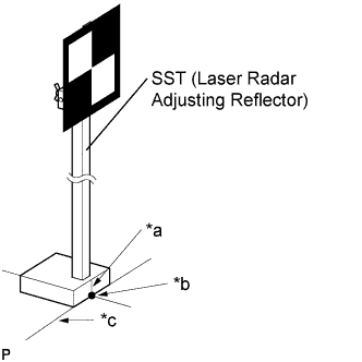
Text in Illustration *a Mark-off Line *b Point C (Placement Point 1) *c Target Placement Line Align the target sheet with the target placement line and align the mark-off line with point C (placement point 1).
-
Check that the screen displays beam axis learning for target 1, then press the "Next" button on the display screen.
-
Text in Illustration *a Mark-off Line *b Point G (Placement Point 2) *c Target Placement Line Align the target sheet with the target placement line, and align the mark-off line with point G (placement point 2).
-
Check that the screen displays beam axis learning for target 2, then press the "Next" button on the display screen.
Note
Within 3 minutes after the screen displays the beam axis learning for target 2, move the target and press the "Next" button on the display screen.
-
Text in Illustration *a Mark-off Line *b Point H (Placement Point 3) *c Target Placement Line Align the target sheet with the target placement line and align the mark-off line with point H (placement point 3).
-
Check that the screen displays beam axis learning for target 3 then press the "Next" button on the display screen.
Note
Within 3 minutes after the screen displays the beam axis learning for target 3, move the target and press the "Next" button on the display screen.
-
Press the "Exit" button to finish beam axis learning mode.
Note
If "Error camera axis adjust" is displayed on the screen, press the "Exit" button. Then after checking the conditions below, turn the engine switch on (IG) and off, and repeat from procedure *1 again.
-
Height of the target.
-
Distance from the lane departure warning camera to the target.
-
Orientation of the target (black area positioned on top right).
-
If surrounding area is bright enough.
-
If black and white patterned objects are placed near the target.
-
-
-