ENGINE SWITCH INSTALLATION

-
INSTALL ENGINE SWITCH
-
Engage the 2 claws to install the engine switch.
-
-
INSTALL SWITCH BASE
-
Connect the connector.
-
Engage the 3 claws to install the switch base.
-
-
INSTALL LOWER NO. 1 INSTRUMENT PANEL FINISH PANEL
-
Connect each connector.
-
Engage the 12 claws, 2 clips and guide.
-
Install the lower No. 1 instrument panel finish panel with the 2 bolts <B>.
-
-
CONNECT HOOD LOCK CONTROL LEVER SUB-ASSEMBLY
-
Engage the claw and 2 guides to connect the hood lock control lever sub-assembly.
-
-
INSTALL INSTRUMENT SIDE PANEL LH
-
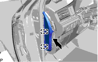
Engage the 2 guides.
-
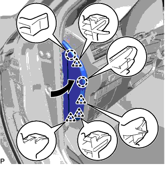
Engage the 2 claws and 4 clips to install the instrument side panel LH as shown in the illustration.
-
-
INSTALL FRONT DOOR OPENING TRIM COVER LH
-
Engage the guide.
-
Engage the 3 claws to install the front door opening trim cover LH.
-
-
INSTALL COWL SIDE TRIM BOARD LH
-
Engage the clip and claw.
-
Install the cowl side trim board LH with the clip.
-
-
INSTALL FRONT DOOR SCUFF PLATE LH
-
Engage the 10 claws to install the front door scuff plate LH.
-
-
INSTALL MULTI-MEDIA MODULE RECEIVER ASSEMBLY WITH BRACKET (w/ Navigation System)
-
INSTALL RADIO RECEIVER ASSEMBLY WITH BRACKET (w/o Navigation System)
-
CONNECT CABLE TO NEGATIVE BATTERY TERMINAL
Note
When disconnecting the cable, some systems need to be initialized after the cable is reconnected Click here.