OIL PUMP INSTALLATION

-
INSTALL TIMING CHAIN COVER SUB-ASSEMBLY
-
Apply a light coat of engine oil to 2 new oil pump gaskets and a new oil hole cover gasket.
-
Install the 2 oil pump gaskets and oil hole cover gasket to the stiffening crankcase assembly.
-
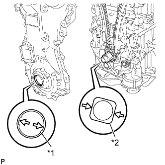
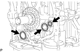
Text in Illustration *1 Drive Rotor Spline *2 Crankshaft Timing Sprocket Align the drive rotor spline and the crankshaft timing sprocket as shown in the illustration.
-
Apply seal packing in a line to the timing chain cover sub-assembly as shown in the following illustration.
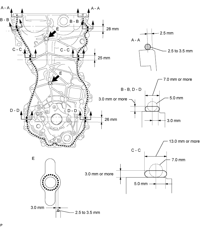
Seal packing Toyota Genuine Seal Packing Black, Three Bond 1207B or equivalent. Apply Seal Packing as Follows Area Seal Packing Diameter (Round) Distance from Edge of Cover to Center of Seal Packing Seal Packing Application Length Seal Packing Dimension (Flat) Dashed Line 2.5 to 3.5 mm (0.0984 to 0.0138 in.) 2.5 mm (0.0984 in.) - - A - A 2.5 to 3.5 mm (0.0984 to 0.0138 in.) 2.5 mm (0.0984 in.) - - B - B 5.0 mm (0.197 in.) 3.0 mm (0.118 in.) 28 mm (1.10 in.) 7.0 mm (0.276 in.) or more wide and 3.0 mm (0.118 in.) or more thick C - C 7.0 mm (0.276 in.) 5.0 mm (0.197 in.) 25 mm (0.984 in.) 13.0 mm (0.512 in.) or more wide and 3.0 mm (0.118 in.) or more thick D - D 5.0 mm (0.197 in.) 3.0 mm (0.118 in.) 26 mm (1.02 in.) 7.0 mm (0.276 in.) or more wide and 3.0 mm (0.118 in.) or more thick E 2.5 to 3.5 mm (0.0984 to 0.0138 in.) 3.0 mm (0.118 in.) - - Note
-
Clean the surfaces with non-residue solvent before applying seal packing.
-
Install the timing chain cover sub-assembly within 3 minutes and tighten the bolts within 10 minutes after applying seal packing.
-
After applying seal packing to the timing chain cover sub-assembly, install the engine mounting bracket RH within 10 minutes.
-
Do not add oil for at least 2 hours after installation.
-
Do not start the engine for at least 2 hours after the installation.
-
-
Temporarily install the timing chain cover sub-assembly with the 17 bolts and 2 nuts.
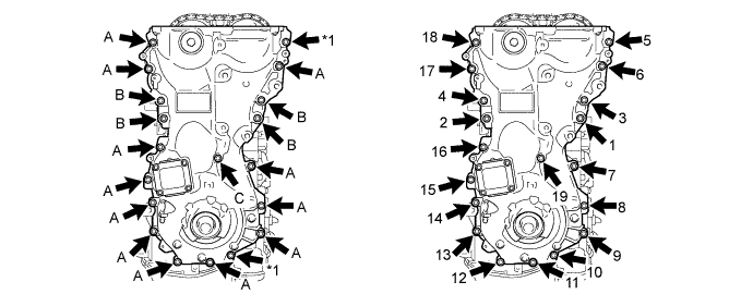
Text in Illustration *1 Nut - - Bolt Length Item Length Thread Diameter Bolt A 30 mm (1.18 in.) 8 mm (0.315 in.) Bolt B 35 mm (1.38 in.) 10 mm (0.394 in.) Bolt C 45 mm (1.77 in.) 8 mm (0.315 in.) Note
Make sure there is no oil on the bolts. If oil is found on any bolt, clean it before installation.
-
Tighten the 17 bolts and 2 nuts in several steps, in the sequence shown in the illustration.
- Torque:
- for bolt A, C and Nut
- 21 N*m { 214 kgf*cm, 15 ft.*lbf }
- for bolt B
- 55 N*m { 561 kgf*cm, 41 ft.*lbf }
-
-
INSTALL ENGINE MOUNTING BRACKET RH
-
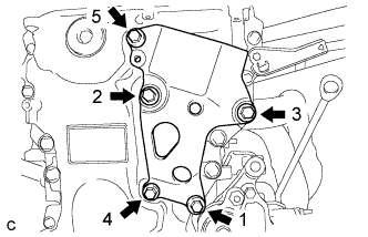
Install the engine mounting bracket RH with the 5 bolts in the order shown in the illustration.
- Torque:
- for bolt 1, 2 and 3
- 55 N*m { 561 kgf*cm, 41 ft.*lbf }
- for bolt 4 and 5
- 21 N*m { 214 kgf*cm, 15 ft.*lbf }
Note
After applying seal packing to the timing chain cover sub-assembly, install the engine mounting bracket RH within 10 minutes.
-
-
INSTALL TIMING CHAIN COVER OIL SEAL
-
Apply MP grease to the lip of a new timing chain cover oil seal.
Note
-
Do not allow foreign matter to contact the lip of the timing chain cover oil seal.
-
Do not allow MP grease to contact the dust seal.
-
-
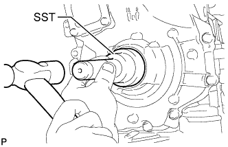
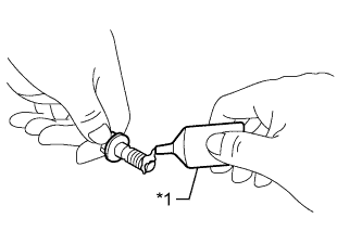
Using SST and a hammer, tap in the timing chain cover oil seal until its surface is flush with the timing chain cover edge.
- SST
- 09223-22010
Note
-
Keep the lip of the timing chain cover oil seal free from foreign matter.
-
Do not tap in the timing chain cover oil seal at an angle.
-
-
INSTALL CRANKSHAFT PULLEY
-
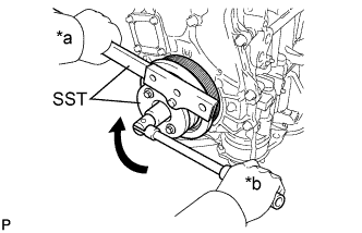
Text in Illustration *a Hold *b Turn Align the crankshaft pulley key with the key groove of the crankshaft pulley.
-
Using SST, hold the crankshaft pulley and install the pulley bolt.
- SST
- 09213-54015
- 09330-00021
- Torque:
- 260 N*m { 2651 kgf*cm, 192 ft.*lbf }
Tech Tips
SST (Crankshaft pulley holding tool) Fixing bolt part No. : 91551-80650(2 pcs)
-
-
INSTALL CRANKSHAFT POSITION SENSOR
-
Clean and degrease the threads of the bolt for the crankshaft position sensor.
-
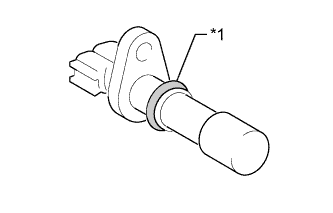
Text in Illustration *1 O-ring Apply a light coat of engine oil to the O-ring of the crankshaft position sensor.
-
Text in Illustration *1 Adhesive Apply adhesive to 2 or 3 threads of the bolt.
Adhesive Toyota Genuine Adhesive 1324, Three Bond 1324 or equivalent. -
Install the crankshaft position sensor with the bolt.
- Torque:
- 6.5 N*m { 66 kgf*cm, 58 in.*lbf }
Note
Make sure that the O-ring is not cracked or moved out of place during installation.
-
Connect the crankshaft position sensor connector.
-
-
INSTALL V-RIBBED BELT TENSIONER ASSEMBLY
-
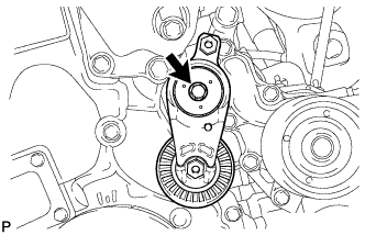
Install the V-ribbed belt tensioner assembly with the bolt.
- Torque:
- 21 N*m { 214 kgf*cm, 15 ft.*lbf }
-
-
INSTALL CYLINDER HEAD COVER SUB-ASSEMBLY
-
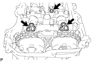
Apply a light coat of engine oil to 3 new camshaft bearing cap oil hole gaskets.
-
Install the 3 camshaft bearing cap oil hole gaskets.
-
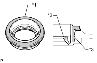
Text in Illustration *1 Upper Surface *2 Inner Lip *3 Outer Lip Visually check the spark plug tube gasket.
OK Area Specified Condition Upper surface No scratches or deformation Outer lip No scratches or deformation Inner lip No scratches Tech Tips
If the result is not as specified, replace the spark plug tube gasket.
-
Install a new cylinder head cover gasket to the cylinder head cover sub-assembly.
Note
Remove any oil from the contact surfaces.
-
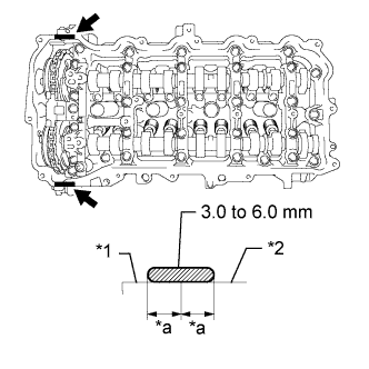
Text in Illustration *1 Timing Chain Cover Sub-assembly *2 Camshaft Housing Sub-assembly *a Application width 5.0 mm (0.197 in.) 
Seal packing Apply seal packing as shown in the illustration.
Seal packing Toyota Genuine Seal Packing Black, Three Bond 1207B or equivalent Standard seal packing diameter 3.0 to 6.0 mm (0.118 to 0.236 in.) Note
-
Remove any oil from the contact surfaces.
-
Install the cylinder head cover sub-assembly within 3 minutes and tighten the bolts within 15 minutes of applying seal packing.
-
-
Align the cylinder head cover sub-assembly with pin A. Then align the cylinder head cover sub-assembly with pin B and install the cylinder head cover sub-assembly.
-
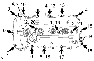
Install 3 new seal washers and the 16 bolts, and then tighten the bolts in the order shown in the illustration.
- Torque:
- 12 N*m { 122 kgf*cm, 9 ft.*lbf }
Note
-
Do not add oil for at least 2 hours after installation.
-
-
INSTALL IGNITION COIL ASSEMBLY
-
Install the 4 ignition coil assemblies with the 4 bolts.
- Torque:
- 10 N*m { 102 kgf*cm, 7 ft.*lbf }
Tech Tips
Perform "Inspection After Repair" after replacing an ignition coil assembly Click here.
-
Connect the 4 ignition coil assembly connectors.
-
-
REMOVE ENGINE STAND