OIL PUMP REMOVAL

Note
Do not remove the oil pump or oil pump relief valve from the timing chain cover sub-assembly.
-
INSTALL ENGINE STAND
-
REMOVE IGNITION COIL ASSEMBLY
-
Disconnect the 4 ignition coil assembly connectors.
-
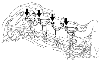
Remove the 4 bolts and 4 ignition coil assemblies.
-
-
REMOVE CYLINDER HEAD COVER SUB-ASSEMBLY
-
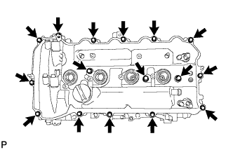
Remove the 16 bolts, 3 seal washers, cylinder head cover sub-assembly and cylinder head cover gasket.
-
Remove the 3 camshaft bearing cap oil hole gaskets.
-
-
REMOVE CRANKSHAFT POSITION SENSOR
-
Disconnect the crankshaft position sensor connector.
-
Remove the bolt and crankshaft position sensor.
-
-
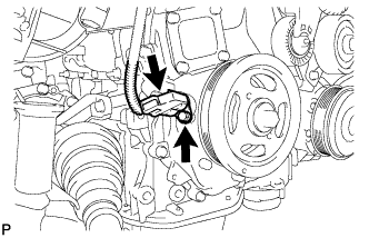
REMOVE CRANKSHAFT PULLEY
-
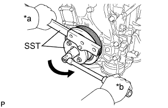
Text in Illustration *a Hold *b Turn Using SST, hold the crankshaft pulley and loosen the pulley bolt. Further loosen the bolt until 2 or 3 threads are screwed into the crankshaft.
- SST
- 09213-54015
- 09330-00021
Tech Tips
SST (Crankshaft pulley holding tool) Fixing bolt part No. : 91551-80650(2 pcs)
-
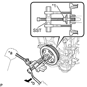
Text in Illustration *1 Pulley Bolt *a Hold *b Turn Using SST and the pulley bolt, remove the crankshaft pulley and pulley bolt.
- SST
- 09950-50013 ( 09951-05010, 09952-05010, 09953-05020, 09954-05011 )
Tech Tips
Apply a lubricant to the threads and end of SST.
-
-
REMOVE ENGINE MOUNTING BRACKET RH
-
Remove the 5 bolts and engine mounting bracket RH.
-
-
REMOVE V-RIBBED BELT TENSIONER ASSEMBLY
-
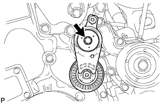
Remove the bolt and V-ribbed belt tensioner assembly.
-
-
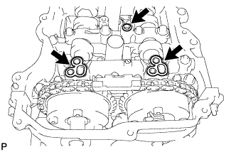
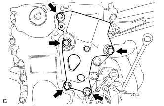
REMOVE TIMING CHAIN COVER SUB-ASSEMBLY
-
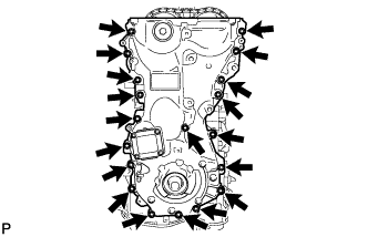
Remove the 17 bolts and 2 nuts.
-

Remove the timing chain cover sub-assembly by prying between the timing chain cover sub-assembly and cylinder head sub-assembly, camshaft housing sub-assembly, cylinder block and stiffening crankcase assembly with a screwdriver as shown in the illustration.
Note
Be careful not to damage the contact surfaces of the cylinder head sub-assembly, camshaft housing sub-assembly, cylinder block, stiffening crankcase assembly or timing chain cover sub-assembly.
Tech Tips
Tape the screwdriver tip before use.
-
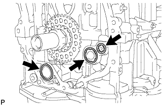
Remove the 2 oil pump gaskets and oil hole cover gasket from the stiffening crankcase assembly.
-
-
REMOVE TIMING CHAIN COVER OIL SEAL
-
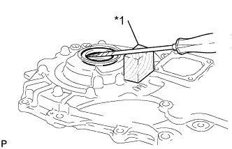
Text in Illustration *1 Wooden Block Using a screwdriver and wooden block, pry out the timing chain cover oil seal.
Note
Do not damage the surface of the timing chain cover oil seal press fit hole.
Tech Tips
Tape the screwdriver tip before use.
-