OIL PUMP REMOVAL

-
REMOVE AUTOMATIC TRANSAXLE ASSEMBLY
-
REMOVE DRIVE PLATE AND RING GEAR SUB-ASSEMBLY
-
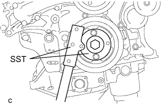
Using SST, hold the crankshaft pulley.
- SST
- 09213-70011 ( 09213-70020 )
- 09330-00021
-
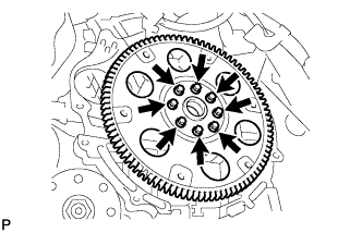
Remove the 8 bolts, front drive plate spacer, drive plate and ring gear sub-assembly and rear drive plate spacer.
-
-
INSTALL ENGINE TO ENGINE STAND
-
Install the engine assembly to an engine stand with the bolts.
-
-
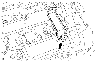
REMOVE ENGINE HANGERS
-
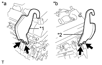
Text in Illustration *1 No. 1 Engine Hanger *2 No. 2 Engine Hanger *a Bank 1 *b Bank 2 Remove the 4 bolts and 2 engine hangers.
-
-
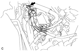
REMOVE INTAKE AIR SURGE TANK ASSEMBLY
-
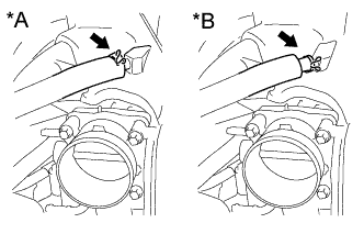
Text in Illustration *A Type A *B Type B Slide the clip and disconnect the ventilation hose from the intake air surge tank assembly.
-
for LHD:
-
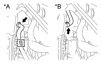
Text in Illustration *A for LHD *B for RHD Slide the clip and disconnect the union to check valve hose from the intake air surge tank assembly.
-
Disengage the hose clamp.
-
-
for RHD:
-
Slide the clip and disconnect the union to check valve hose from the intake air surge tank assembly.
-
-
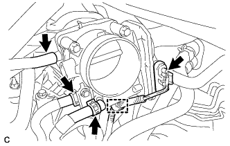
Disconnect the throttle body assembly connector.
-
Disengage the wire harness clamp.
-
Slide the 2 clips and disconnect the 2 water by-pass hoses from the throttle body assembly.
-
Disconnect the fuel vapor feed hose from the intake air surge tank assembly.
-
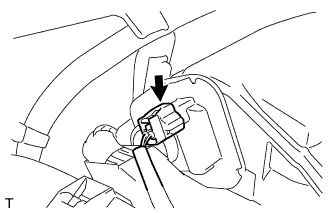
Disconnect the intake air control valve assembly connector.
-
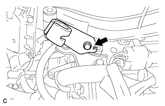
Remove the bolt and vacuum hose clamp from the throttle body bracket.
-
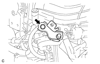
Remove the bolt and separate the throttle body bracket from the intake air surge tank assembly.
-
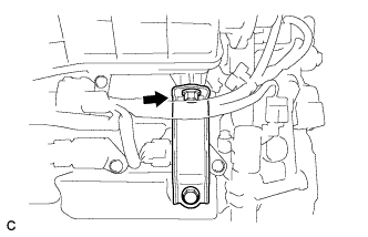
Remove the bolt and separate the No. 1 surge tank stay from the intake air surge tank assembly.
-
Remove the 2 nuts from the intake air surge tank assembly.
-
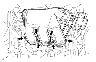
Using a 5 mm hexagon socket wrench, remove the 4 bolts from the intake air surge tank assembly.
-
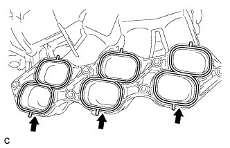
Remove the intake air surge tank assembly and 3 gaskets.
-
-
REMOVE NO. 1 SURGE TANK STAY
-
Remove the bolt and No. 1 surge tank stay.
-
-
REMOVE THROTTLE BODY BRACKET
-
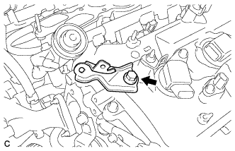
Remove the bolt and throttle body bracket.
-
-
REMOVE IGNITION COIL ASSEMBLY
-
Remove the nut.
-
Disconnect the 2 harness clamps.
-
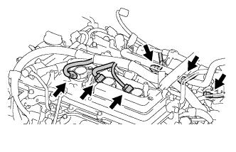
Disconnect the 6 ignition coil assembly connectors.
-
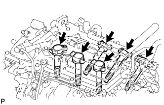
Remove the 6 bolts and 6 ignition coil assemblies.
-
-
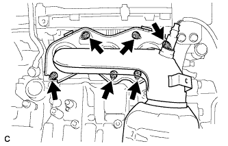
REMOVE EXHAUST MANIFOLD SUB-ASSEMBLY RH
-
Uniformly loosen and remove the 6 nuts.
-
Remove the exhaust manifold sub-assembly RH and gasket.
-
-
REMOVE NO. 2 ENGINE OIL LEVEL DIPSTICK GUIDE
-
Remove the engine oil level dipstick.
-
Remove the bolt and No. 2 engine oil level dipstick guide.
-
Remove the O-ring from the No. 2 engine oil level dipstick guide.
-
-
REMOVE NO. 2 MANIFOLD STAY
-
Remove the bolt, nut and No. 2 manifold stay.
-
-
REMOVE NO. 2 EXHAUST MANIFOLD HEAT INSULATOR
-
Remove the 3 bolts and No. 2 exhaust manifold heat insulator.
-
-
REMOVE EXHAUST MANIFOLD SUB-ASSEMBLY LH
-
Uniformly loosen and remove the 6 nuts.
-
Remove the exhaust manifold sub-assembly LH and gasket.
-
-
REMOVE V-RIBBED BELT TENSIONER ASSEMBLY
-
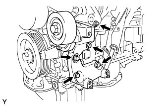
Remove the 5 bolts and V-ribbed belt tensioner assembly.
-
-
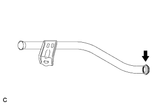
SEPARATE OIL COOLER PIPE (w/ Oil Cooler)
-
Remove the bolt and 2 nuts, and disconnect the oil cooler pipe from the oil pan sub-assembly.
-
Remove the gasket from the oil pan sub-assembly.
-
-
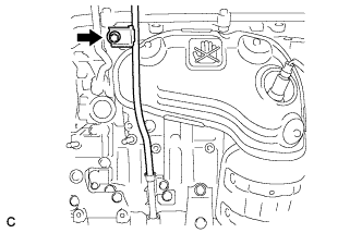
REMOVE ENGINE OIL LEVEL DIPSTICK GUIDE
-
w/ Oil Cooler:
-
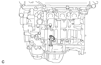
Remove the engine oil level dipstick guide.
-
-
w/o Oil Cooler:
-
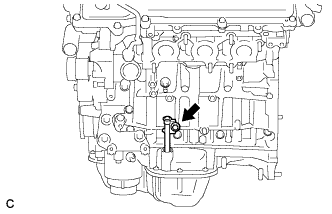
Remove the bolt and engine oil level dipstick guide.
-
-
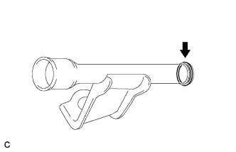
Remove the O-ring.
-
-
REMOVE NO. 2 TIMING GEAR COVER
-
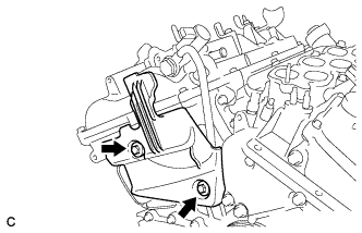
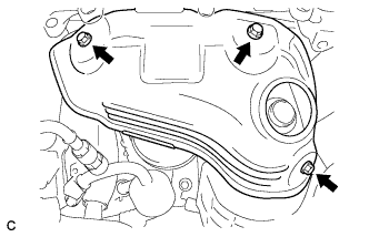
Remove the 2 bolts and No. 2 timing gear cover.
-
-
REMOVE WATER PUMP PULLEY
-
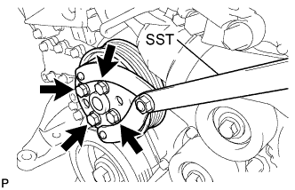
Using SST, hold the water pump pulley.
- SST
- 09960-10010 ( 09962-01000, 09963-00700 )
-
Remove the 4 bolts and water pump pulley.
-
-
REMOVE NO. 2 IDLER PULLEY SUB-ASSEMBLY
-
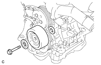
Remove the bolt, No. 2 idler pulley cover plate, No. 2 idler pulley sub-assembly and idler pulley cover plate.
-
-
REMOVE NO. 1 VACUUM SWITCHING VALVE
-
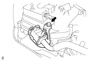
Remove the bolt and No. 1 vacuum switching valve.
-
-
REMOVE CRANK POSITION SENSOR
-
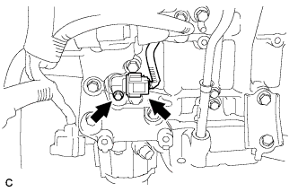
Disconnect the crank position sensor connector.
-
Remove the bolt and crank position sensor.
-
-
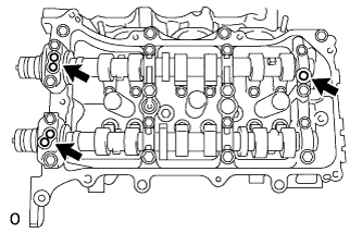
REMOVE NO. 1 OIL PIPE
-
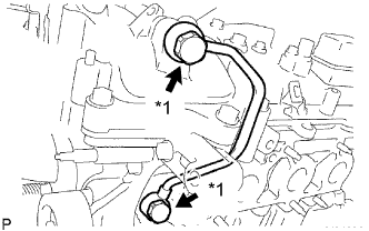
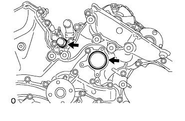
Text in Illustration *1 Oil Pipe Union Remove the 2 oil pipe unions, 3 gaskets and No. 1 oil pipe.
-
Remove the oil control valve filter LH.
-
-
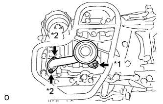
REMOVE OIL PIPE
-
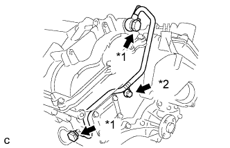
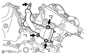
Text in Illustration *1 Oil Pipe Union *2 Bolt Remove the bolt.
-
Remove the 2 oil pipe unions, 3 gaskets and oil pipe.
-
Remove the oil control valve filter RH.
-
-
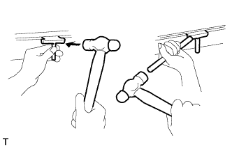
REMOVE CRANKSHAFT PULLEY
-
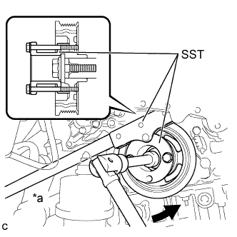
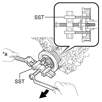
Text in Illustration *a Hold 
Turn Using SST, loosen the crankshaft pulley bolt.
- SST
- 09213-70011 ( 09213-70020 )
- 09330-00021
-
Text in Illustration *a Hold Turn Using SST, remove the crankshaft pulley bolt and crankshaft pulley.
- SST
- 09950-50013 ( 09951-05010, 09952-05010, 09953-05020, 09954-05021 )
-

Remove the pulley set key from the crankshaft.
-
-
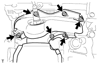
REMOVE NO. 1 FRONT ENGINE MOUNTING BRACKET LH
-
Remove the 6 bolts and No. 1 front engine mounting bracket LH.
-
Using an E8 "TORX" socket wrench, remove the 2 stud bolts.
-
-
REMOVE WATER INLET HOUSING
-
Remove the 2 nuts, water inlet and thermostat.
-
Remove the gasket.
-
Remove the 2 stud bolts.
-
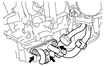
Slide the clip and disconnect the No. 1 water bypass hose from the water inlet housing.
-
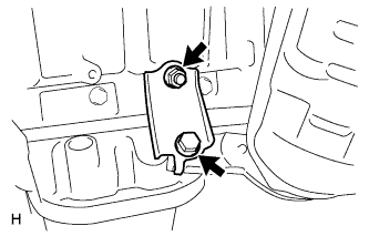
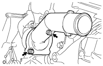
Text in Illustration *1 Nut *2 Bolt Remove the drain cock plug.
-
Remove the drain cock assembly.
-
Remove the 2 bolts, nut, and water inlet housing.
-
Remove the 2 O-rings.
-
-
REMOVE CYLINDER HEAD COVER SUB-ASSEMBLY
-
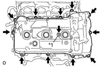
Text in Illustration *1 Seal Washer Remove the 12 bolts, seal washer, cylinder head cover sub-assembly and cylinder head cover gasket.
-
Remove the 3 gaskets.
-
-
REMOVE CYLINDER HEAD COVER SUB-ASSEMBLY LH
-
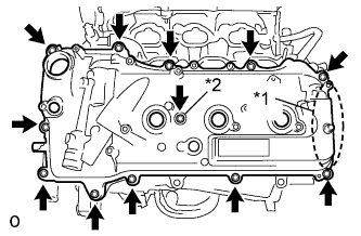
Text in Illustration *1 Baffle Plate *2 Seal Washer Remove the 12 bolts, seal washer, cylinder head cover sub-assembly LH and No. 2 cylinder head cover gasket.
Note
The baffle plate is located on the back of the portion shown in the illustration. Do not damage the baffle plate when removing the cylinder head cover sub-assembly LH.
-
Remove the 3 gaskets.
-
-
REMOVE NO. 2 OIL PAN SUB-ASSEMBLY
-
Text in Illustration *1 Nut Remove the 16 bolts and 2 nuts.
-
Insert the blade of on oil pan seal cutter between the oil pan sub-assembly and No. 2 oil pan sub-assembly. Cut through the applied sealer and remove the No. 2 oil pan sub-assembly.
Note
Be careful not to damage the contact surfaces of the oil pan sub-assembly and No. 2 oil pan sub-assembly.
-
Using an E6 "TORX" socket wrench, remove the 2 stud bolts.
-
-
REMOVE OIL STRAINER SUB-ASSEMBLY
-
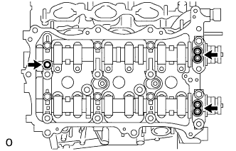
Text in Illustration *1 Bolt *2 Nut Remove the bolt, 2 nuts, oil strainer sub-assembly and gasket.
-
Using an E6 "TORX" socket wrench, remove the 2 stud bolts.
-
-
REMOVE OIL PAN SUB-ASSEMBLY
-
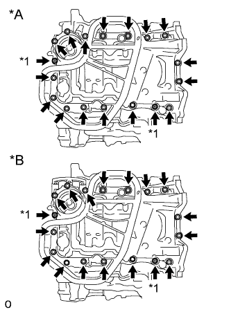
Text in Illustration *A w/o Oil Cooler *B w/ Oil Cooler *1 Nut Remove the 16 bolts and 2 nuts.
Tech Tips
Be sure to clean the bolts and stud bolts and check the threads for cracks or other damage.
-
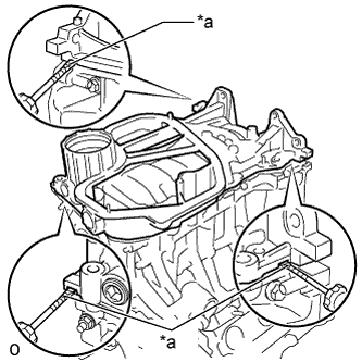
Text in Illustration *a Protective Tape Remove the oil pan sub-assembly by prying between the oil pan sub-assembly and cylinder block sub-assembly with a screwdriver.
Note
Be careful not to damage the contact surfaces of the cylinder block sub-assembly and oil pan sub-assembly.
Tech Tips
Tape the screwdriver tip before use.
-
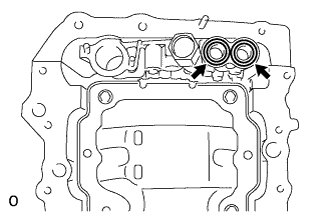
Remove the 2 O-rings.
-
w/ Oil Cooler:
-
Using an E8 "TORX" socket wrench, remove the 4 stud bolts.
-
-
w/o Oil Cooler:
-
Using an E8 "TORX" socket wrench, remove the 2 stud bolts.
-
-
-
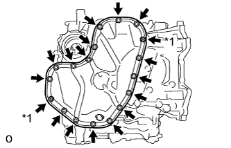
REMOVE TIMING CHAIN COVER SUB-ASSEMBLY
-
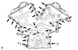
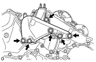
Text in Illustration *1 Nut Remove the 23 bolts and 2 nuts shown in the illustration.
-
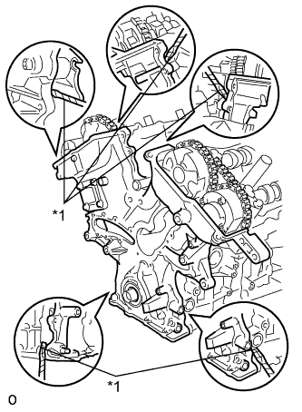
Text in Illustration *1 Protective Tape Remove the timing chain cover sub-assembly by prying between the timing chain cover sub-assembly and cylinder head or cylinder block with a screwdriver.
Note
Be careful not to damage the contact surfaces of the cylinder head, cylinder block and timing chain cover sub-assembly.
Tech Tips
Tape the screwdriver tip before use.
-
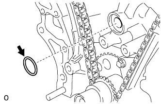
Remove the gasket.
-
-
REMOVE TIMING CHAIN CASE OIL SEAL
-
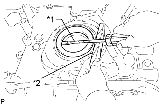
Text in Illustration *1 Protective Tape *2 Wooden Block Using a screwdriver and wooden block, pry out the timing chain case oil seal.
Tech Tips
Tape the screwdriver tip before use.
-