FRONT CONSOLE BOX DISASSEMBLY

-
REMOVE SWITCH BASE
-
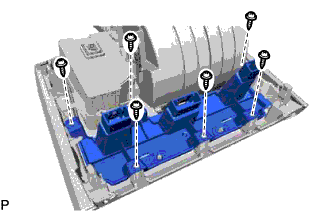
Remove the 6 screws and switch base.
-
-
REMOVE INSTRUMENT PANEL CUP HOLDER
-
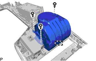
Remove the 3 screws.
-
Disengage the guide and remove the instrument panel cup holder.
-
-
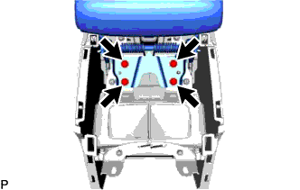
REMOVE SHIFT POSITION INDICATOR
-
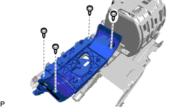
Remove the 4 screws and shift position indicator.
-
-
REMOVE INSTRUMENT PANEL CUP HOLDER SUB-ASSEMBLY
-
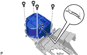
Remove the 4 screws.
-
Disengage the claw and remove the instrument panel cup holder sub-assembly.
-
-
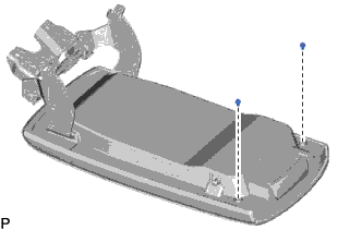
REMOVE CONSOLE COMPARTMENT DOOR SUB-ASSEMBLY
-
Remove the 4 screws and console compartment door sub-assembly.
-
-
REMOVE NO. 1 CONSOLE COMPARTMENT DOOR CUSHION
-
Remove the 2 No. 1 console compartment door cushions.
-
-
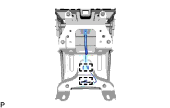
REMOVE NO. 2 CONSOLE BOX DUCT
-
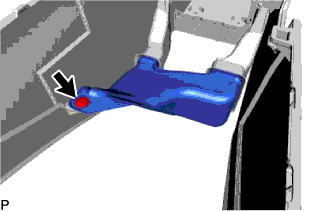
Remove the clip and No. 2 console box duct.
-
-
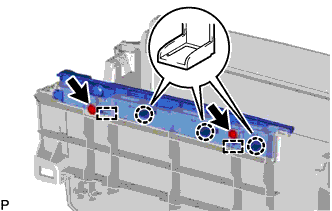
REMOVE NO. 1 CONSOLE BOX RETAINER
-
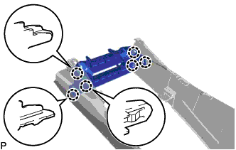
Disengage the 6 claws and remove the No. 1 console box retainer.
-
-
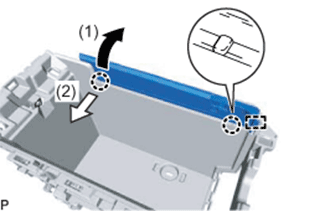
REMOVE NO. 1 BOX SIDE PANEL
-
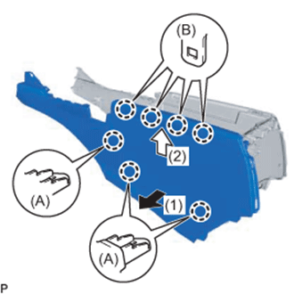
Pull the No. 1 box side panel in the direction indicated by the arrow (1) shown in the illustration to disengage the 3 claws (A).
-
Pull the No. 1 box side panel in the direction indicated by the arrow (2) shown in the illustration to disengage the 4 claws (B) and remove the No. 1 box side panel.
-
-
REMOVE NO. 2 BOX SIDE PANEL
Tech Tips
Use the same procedure as for the No. 1 box side panel.
-
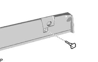
REMOVE NO. 3 CONSOLE BOX DUCT
-
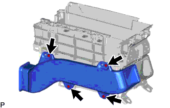
Remove the 4 screws and No. 3 console box duct.
-
-
REMOVE NO. 4 CONSOLE BOX DUCT
Tech Tips
Use the same procedure as for the No. 3 console box duct.
-
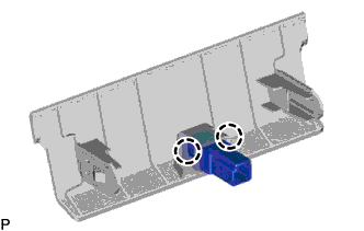
REMOVE FRONT UPPER CONSOLE PANEL GARNISH
-
Disconnect the connector.
-
Disengage the 2 claws and remove the front upper console panel garnish.
-
-
REMOVE CONSOLE BOX ILLUMINATION LIGHT ASSEMBLY
-
Disengage the 2 claws and remove the console box illumination light assembly.
-
-
REMOVE NO. 2 INSTRUMENT PANEL WIRE
-
Disengage the 2 clamps and remove the No. 2 instrument panel wire.
-
-
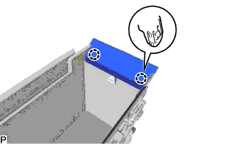
REMOVE UPPER NO. 1 BOX PLATE
-
Remove the 2 screws.
-
Disengage the 3 claws and 2 guides.
-
Pull the upper No. 1 box plate in the direction indicated by the arrow (1) shown in the illustration.
-
Pull the upper No. 1 box plate in the direction indicated by the arrow (2) shown in the illustration to disengage the 2 claws.
-
Disengage the guide and remove the upper No. 1 box plate.
-
-
REMOVE UPPER NO. 2 BOX PLATE
Tech Tips
Use the same procedure as for the upper No. 1 box plate.
-
REMOVE NO. 2 CONSOLE COMPARTMENT DOOR CUSHION
-
Remove the No. 2 console compartment door cushion.
Tech Tips
Use the same procedure for the RH side and LH side.
-