INSTRUMENT PANEL SAFETY PAD REMOVAL

-
PRECAUTION
Note
After turning the engine switch off, waiting time may be required before disconnecting the cable from the negative (-) battery terminal. Therefore, make sure to read the disconnecting the cable from the negative (-) battery terminal notices before proceeding with work Click here.
-
DISCONNECT CABLE FROM NEGATIVE BATTERY TERMINAL
-
for Power Tilt and Power Telescopic Steering Column:
-
Disable the auto away/return function by changing the customize parameter Click here.
Note
Record the current customize parameter setting (whether the auto away/return function is enabled or disabled) in order to restore the current setting after finishing this operation.
Tech Tips
Performing the above operation disables the auto away/return function when the engine switch is turned off.
-
Turn the engine switch on (IG). Operate the tilt and telescopic switch to fully extend and lower the steering column assembly.
-
Turn the engine switch off and disconnect the cable from the negative (-) battery terminal.
CAUTION:
Wait at least 90 seconds after disconnecting the cable from the negative (-) battery terminal to disable the SRS system.
Note
When disconnecting the cable, some systems need to be initialized after the cable is reconnected Click here.
-
-
-
REMOVE HORN BUTTON ASSEMBLY
-
REMOVE STEERING WHEEL ASSEMBLY
-
Disconnect the connectors from the spiral cable sub-assembly.
-
w/ Steering Heater:
-
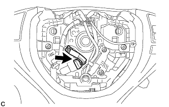
Disconnect the connector.
-
-
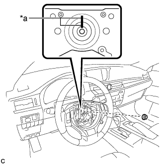
Text in Illustration *a Matchmark Remove the steering wheel assembly set nut.
-
Put matchmarks on the steering wheel assembly and steering main shaft.
-
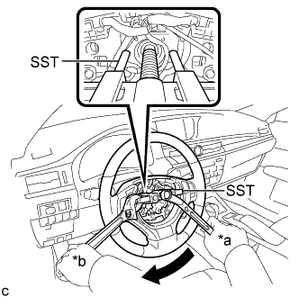
Text in Illustration *a Turn *b Hold Using SST, remove the steering wheel assembly.
- SST
- 09950-50013 ( 09951-05010, 09952-05010, 09953-05020, 09954-05070 )
Note
Apply a small amount of grease to the threads and tip of SST (09953-05020) before use.
-
-
REMOVE LOWER STEERING COLUMN COVER (for Manual Tilt and Manual Telescopic Steering Column)
-
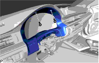
Remove the 2 screws.
-
Push the right and left sides of the lower steering column cover, and disengage the 2 claws.
-
Insert a finger into the opening of the tilt lever of the lower steering column cover to disengage the claw and remove the lower steering column cover.
-
-
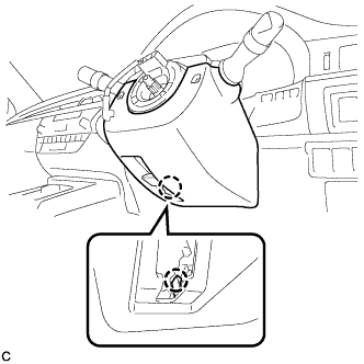
REMOVE LOWER STEERING COLUMN COVER (for Power Tilt and Power Telescopic Steering Column)
-
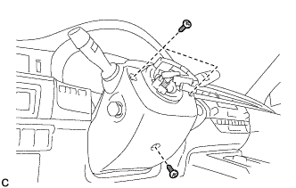
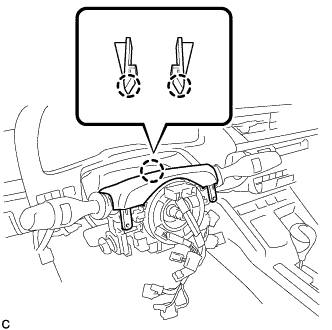
Remove the 3 screws.
-
Push the right and left sides of the lower steering column cover, and disengage the 2 claws to remove the lower steering column cover.
Note
Do not damage the tilt and telescopic switch.
-
-
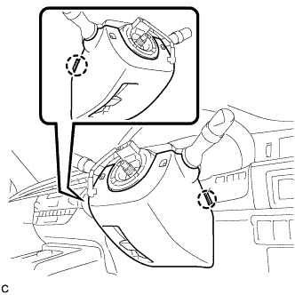
REMOVE UPPER STEERING COLUMN COVER
-
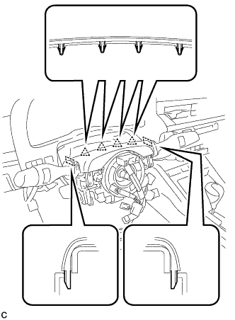
Disengage the 4 clips and 2 guides from the upper steering column cover.
-
Disengage the 2 claws to remove the upper steering column cover.
-
-
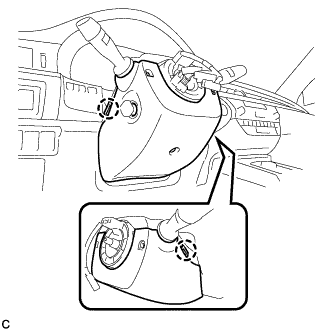
REMOVE TURN SIGNAL SWITCH ASSEMBLY WITH SPIRAL CABLE SUB-ASSEMBLY
Note
-
Do not replace the spiral cable with sensor sub-assembly with the battery connected and the engine switch on (IG).
-
Do not rotate the spiral cable with sensor sub-assembly without the steering wheel with the battery connected and the engine switch on (IG).
-
Ensure that the steering wheel is installed and aligned straight when inspecting the steering sensor.
-
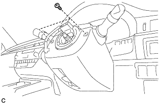
Disconnect the connectors from the turn signal switch assembly with spiral cable sub-assembly.
-
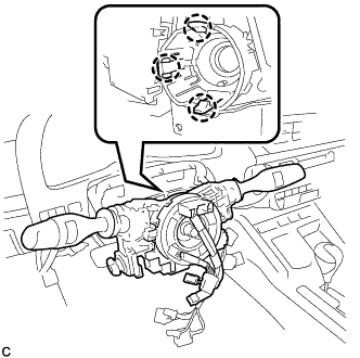
Disengage the 3 claws to remove the turn signal switch assembly with spiral cable sub-assembly from the steering post assembly.
-
-
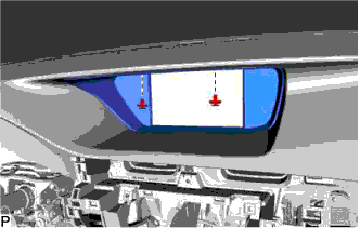
REMOVE INSTRUMENT CLUSTER FINISH PANEL SUB-ASSEMBLY
-
Remove the 2 screws <E>.
-
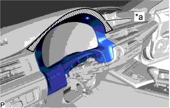
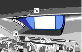
Text in Illustration *a Protective Tape Apply protective tape to the area shown in the illustration.
-
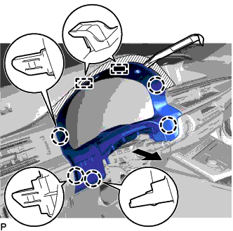
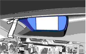
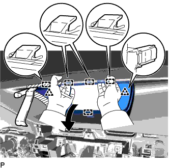
Using a moulding remover, disengage the 5 claws and 2 guides as shown in the illustration.
-
Disconnect the connector to remove the instrument cluster finish panel sub-assembly.
-
-
REMOVE CENTER INSTRUMENT CLUSTER FINISH PANEL GARNISH
-
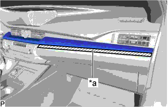
Text in Illustration *a Protective Tape Apply protective tape to the area shown in the illustration.
-
Using a moulding remover, disengage the 10 claws and 2 clips as shown in the illustration.
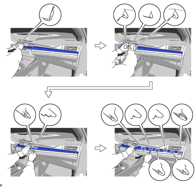
-
Disconnect the connector to remove the center instrument cluster finish panel garnish.
-
-
REMOVE NO. 2 INSTRUMENT PANEL REGISTER ASSEMBLY
-
Using a moulding remover, disengage the 11 claws and clip as shown in the illustration.
-
Disconnect the connector to remove the No. 2 instrument panel register assembly.
-
-
REMOVE LOWER CENTER INSTRUMENT PANEL FINISH PANEL
-
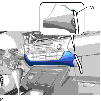
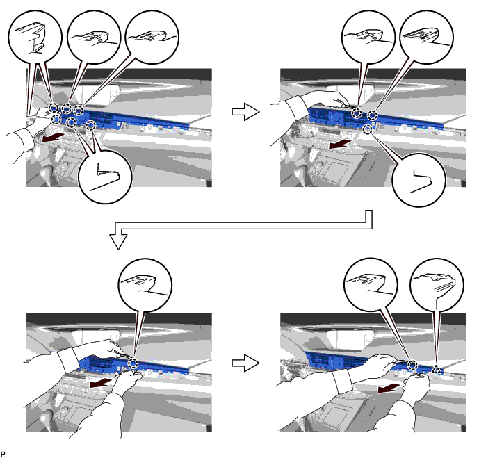
Text in Illustration *a Lower Center Instrument Panel Finish Panel Hole Insert a moulding remover as shown in the illustration.
-
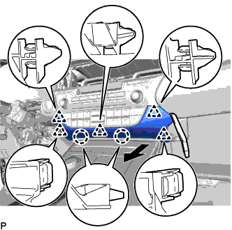
Using a moulding remover, disengage the 2 claws and 5 clips and remove the lower center instrument panel finish panel as shown in the illustration.
-
-
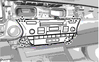
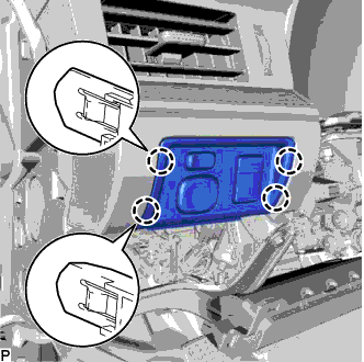
REMOVE RADIO RECEIVER ASSEMBLY WITH BRACKET (w/o Navigation System)
-
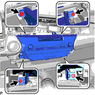
Remove the 4 bolts.
-
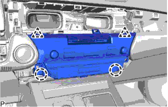
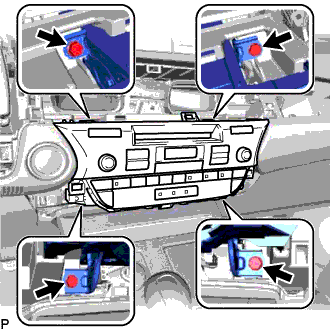
Pull the radio receiver assembly with bracket toward the rear of the vehicle and disengage the 2 clips and 2 claws.
-
Disconnect each connector and remove the radio receiver assembly with bracket.
-
-
REMOVE MULTI-MEDIA MODULE RECEIVER ASSEMBLY WITH BRACKET (w/ Navigation System)
-
Remove the 4 bolts.
-
Pull the multi-media module receiver assembly with bracket toward the rear of the vehicle and disengage the 2 clips and 2 claws.
-
Disconnect each connector and remove the multi-media module receiver assembly with bracket.
-
-
REMOVE FRONT DOOR SCUFF PLATE LH
-
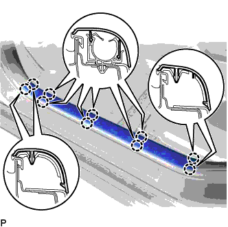
Disengage the 10 claws and remove the front door scuff plate LH.
-
-
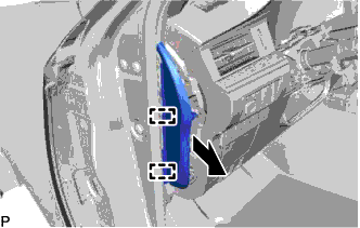
REMOVE COWL SIDE TRIM BOARD LH
-
Remove the clip.
-
Disengage the claw and clip, and remove the cowl side trim board LH.
-
-
REMOVE FRONT DOOR OPENING TRIM COVER LH
-
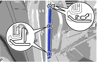
Disengage the 3 claws.
-
Disengage the guide and remove the front door opening trim cover LH.
-
-
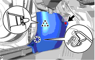
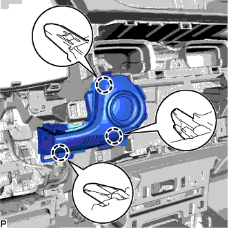
REMOVE INSTRUMENT SIDE PANEL LH
-
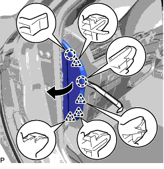
Using a moulding remover, disengage the 2 claws and 4 clips as shown in the illustration.
-
Disengage the 2 guides and remove the instrument side panel LH as shown in the illustration.
-
-
DISCONNECT HOOD LOCK CONTROL LEVER SUB-ASSEMBLY
-
Disengage the claw and 2 guides to disconnect the hood lock control lever sub-assembly.
-
-
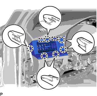
REMOVE LOWER NO. 1 INSTRUMENT PANEL FINISH PANEL
-
for LHD:
-
Remove the 2 bolts <B>.
-
Disengage the 12 claws, 2 clips and guide.
-
Disconnect each connector and disengage each clamp to remove the lower No. 1 instrument panel finish panel.
-
-
for RHD:
-
Text in Illustration *a Protective Tape Using a screwdriver, disengage the 2 claws and open the cover.
Tech Tips
Tape the screwdriver tip before use.
-
Remove the 2 bolts <B>.
-
Disengage the 6 claws, 3 clips and guide.
-
Disconnect each connector and disengage each clamp to remove the lower No. 1 instrument panel finish panel.
-
-
-
REMOVE COMBINATION METER ASSEMBLY
-
Remove the 2 screws.
-
Disengage the 2 clips.
-
Disconnect the 2 connectors to remove the combination meter assembly.
-
-
REMOVE NO. 1 SWITCH HOLE BASE
-
Disengage the 4 claws.
-
Disconnect each connector to remove the No. 1 switch hole base.
-
-
REMOVE NO. 1 INSTRUMENT PANEL REGISTER ASSEMBLY
-
Disengage the 6 claws and 2 guides to remove the No. 1 instrument panel register assembly.
-
-
REMOVE SWITCH BASE
-
for LHD:
-
Disengage the 3 claws.
-
Disconnect the connector to remove the switch base.
-
-
for RHD:
-
Disengage the 4 claws.
-
Disconnect the connector to remove the switch base.
-
-
-
REMOVE CENTER INSTRUMENT CLUSTER FINISH PANEL SUB-ASSEMBLY
-
Remove the 2 clips.
-
Text in Illustration *a Protective Tape Apply protective tape to the areas shown in the illustration.
-
Insert a moulding remover as shown in the illustration.
-
Pull the center instrument cluster finish panel sub-assembly in the direction indicated by the arrow shown in the illustration to disengage the 2 clips and 5 guides, and remove the center instrument cluster finish panel sub-assembly.
-
-
REMOVE MULTI-DISPLAY ASSEMBLY
-
Remove the 2 screws.
-
Pull the multi-display assembly in the direction indicated by the arrow to disengage the 2 clips.
-
Disconnect each connector and remove the multi-display assembly.
-
-
REMOVE REAR CONSOLE BOX ASSEMBLY
-
REMOVE FRONT DOOR SCUFF PLATE RH
Tech Tips
Use the same procedure as for the LH side Click here.
-
REMOVE COWL SIDE TRIM BOARD RH
Tech Tips
Use the same procedure as for the LH side Click here.
-
REMOVE FRONT DOOR OPENING TRIM COVER RH
Tech Tips
Use the same procedure as for the LH side Click here.
-
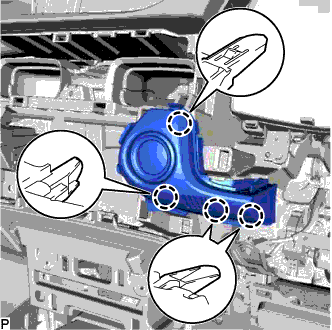
REMOVE INSTRUMENT SIDE PANEL RH
-
Using a moulding remover, disengage the 2 claws and 4 clips as shown in the illustration.
-
Disengage the 2 guides and remove the instrument side panel RH as shown in the illustration.
-
-
REMOVE NO. 2 INSTRUMENT PANEL UNDER COVER SUB-ASSEMBLY
-
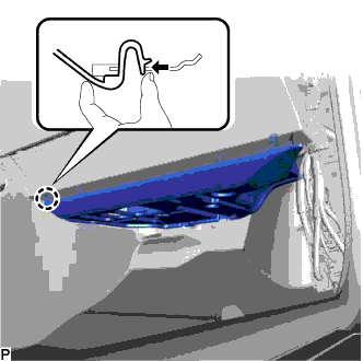
Disengage the claw as shown in the illustration.
-
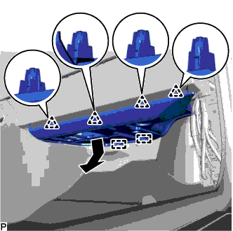
Disengage the 4 clips and 2 guides as shown in the illustration.
-
Disconnect the connector to remove the No. 2 instrument panel under cover sub-assembly.
-
-
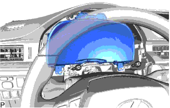
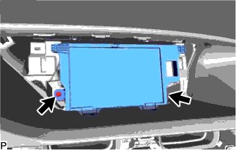
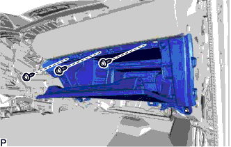
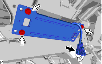
REMOVE LOWER NO. 2 INSTRUMENT PANEL AIRBAG ASSEMBLY
CAUTION:
When storing the lower No. 2 instrument panel airbag assembly, keep the airbag deployment side facing upward.
-
Check that the engine switch is off.
-
Check that the cable is disconnected from the negative (-) battery terminal.
CAUTION:
Wait at least 90 seconds after disconnecting the cable from the negative (-) battery terminal to disable the SRS system.
-

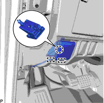
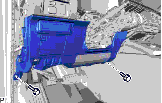
Remove the 3 bolts.
-
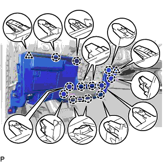
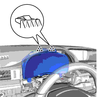
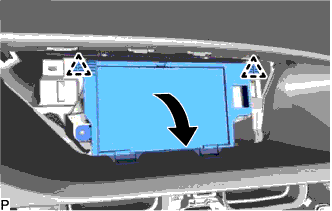
Disengage the 5 claws and 2 guides to separate the lower No. 2 instrument panel airbag assembly.
Note
When removing the lower No. 2 instrument panel airbag assembly, do not pull the airbag wire harness.
-

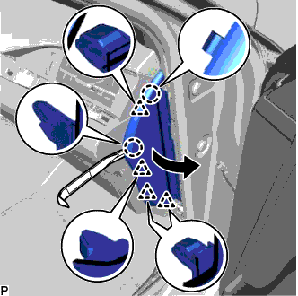
Text in Illustration *1 Protective Tape *2 Airbag Connector *3 Airbag Connector Lock Using a screwdriver with its tip wrapped with protective tape, release the airbag connector lock.
-
Disconnect the airbag connector to remove the lower No. 2 instrument panel airbag assembly.
Note
When disconnecting any airbag connector, take care not to damage the airbag wire harness.
-
-
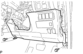
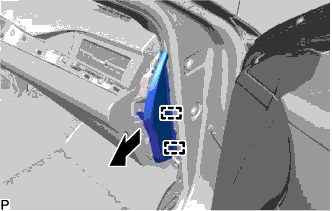
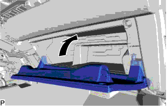
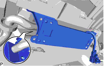
REMOVE INSTRUMENT PANEL BOX DOOR COVER
-

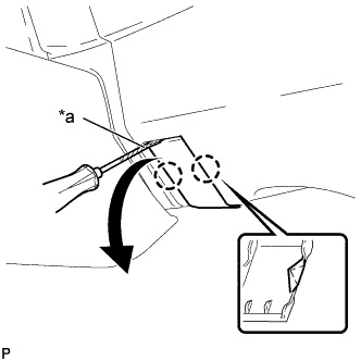
Open the lower instrument panel sub-assembly door as shown in the illustration.
-
Using a moulding remover, disengage the 4 claws and remove the instrument panel box door cover as shown in the illustration.
-
-
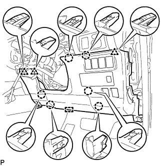
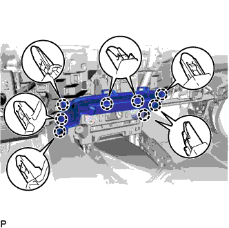
REMOVE LOWER INSTRUMENT PANEL SUB-ASSEMBLY
-
Remove the 3 screws <E>.
-
Close the lower instrument panel sub-assembly door as shown in the illustration.
-
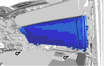
Remove the 2 screws <E>.
-
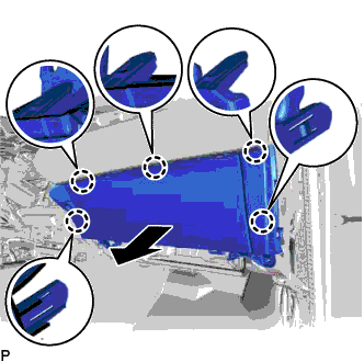
Disengage the 5 claws as shown in the illustration.
-
Disconnect each connector and remove the lower instrument panel sub-assembly.
-
-
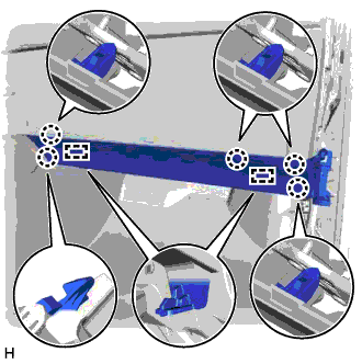
REMOVE NO. 3 INSTRUMENT PANEL REGISTER ASSEMBLY
-
Disengage the 4 claws, 2 clips and 2 guides and remove the No. 3 instrument panel register assembly.
-
-
REMOVE FRONT PILLAR GARNISH LH
-
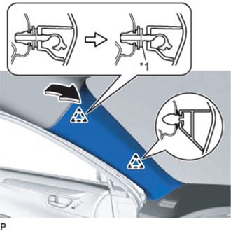
Text in Illustration *1 Front Pillar Garnish Clip Pull the upper part of the garnish toward the inside of the cabin and disengage the garnish from the base of the 2 clips.
Tech Tips
Make the front pillar garnish LH hang down from the front pillar garnish clip.
-
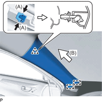
While pushing the tabs on the front pillar garnish clip in the direction indicated by the arrow (A) shown in the illustration, disengage the front pillar garnish clip.
-
Pull the garnish in the direction indicated by the arrow (B) shown in the illustration to disengage the 2 guides and remove the front pillar garnish LH.
-
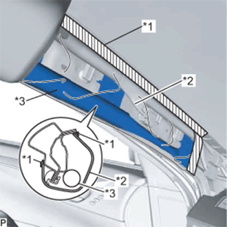
Text in Illustration *1 Adhesive Tape *2 Protective Cover *3 Curtain Shield Airbag Assembly Protect the curtain shield airbag assembly.
-
Cover the airbag with a piece of cloth or nylon and secure the edges of the cover with tape as shown in the illustration.
Note
Cover the curtain shield airbag with a protective cover as soon as the front pillar garnish LH is removed.
-
-
-
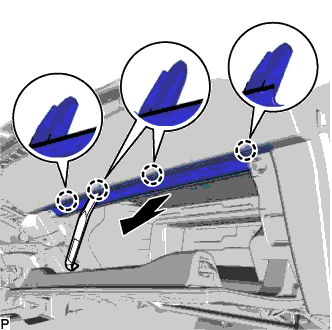
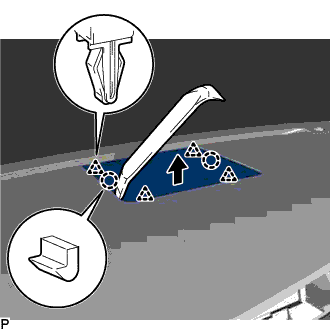
REMOVE NO. 1 INSTRUMENT PANEL SPEAKER PANEL SUB-ASSEMBLY
-

Using a moulding remover, disengage the 2 clips as shown in the illustration.
-
Disengage the 3 guides to remove the No. 1 instrument panel speaker panel sub-assembly as shown in the illustration.
-
-
REMOVE FRONT NO. 2 SPEAKER ASSEMBLY (for LH Side)
-
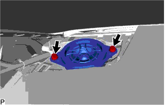
Remove the 2 bolts.
-
Lift the front No. 2 speaker assembly and disconnect the connector to remove it.
Note
Do not touch the speaker cone.
Tech Tips
Use the same procedure for the RH side and LH side.
-
-
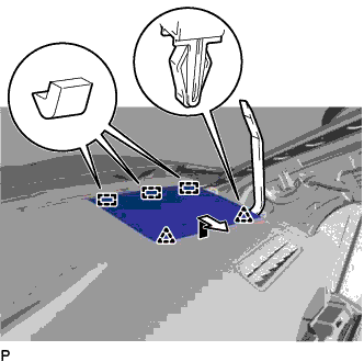
REMOVE NO. 1 SPEAKER OPENING COVER ASSEMBLY
-
Using a moulding remover, disengage the 2 claws and 4 clips and remove the No. 1 speaker opening cover assembly as shown in the illustration.
-
-
REMOVE FRONT NO. 3 SPEAKER ASSEMBLY
-
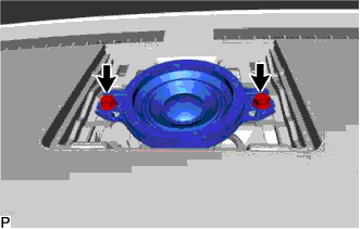
Remove the 2 bolts.
-
Lift the front No. 3 speaker assembly and disconnect the connector to remove it.
Note
Do not touch the speaker cone.
-
-
REMOVE FRONT PILLAR GARNISH RH
Tech Tips
Use the same procedure as for the LH side Click here.
-
REMOVE NO. 2 INSTRUMENT PANEL SPEAKER PANEL SUB-ASSEMBLY
-
Using a moulding remover, disengage the 2 clips as shown in the illustration.
-
Disengage the 3 guides to remove the No. 2 instrument panel speaker panel sub-assembly as shown in the illustration.
-
-
REMOVE FRONT NO. 2 SPEAKER ASSEMBLY (for RH Side)
Tech Tips
Use the same procedure as for the LH side Click here.
-
REMOVE NO. 1 ION GENERATOR SUB-ASSEMBLY (w/ Ion Generator)
-
Disengage the clamp.
-
Disconnect the connector.
-
Remove the 3 screws.
-
Disconnect the ion generator assembly as shown in the illustration and remove the ion generator assembly.
-
-
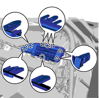
REMOVE INSTRUMENT PANEL FINISH PANEL SUB-ASSEMBLY
-
Disengage the 8 claws to remove the instrument panel finish panel sub-assembly.
-
-
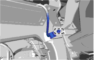
DISCONNECT NO. 2 INSTRUMENT PANEL WIRE
-
Check that the engine switch is off.
-
Check that the cable is disconnected from the negative (-) battery terminal.
CAUTION:
Wait at least 90 seconds after disconnecting the cable from the negative (-) battery terminal to disable the SRS system.
-
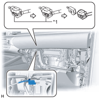
Text in Illustration *1 Slider Slide the slider to release the lock, and then disconnect the connector.
Note
When disconnecting any airbag connector, take care not to damage the airbag wire harness.
-
-
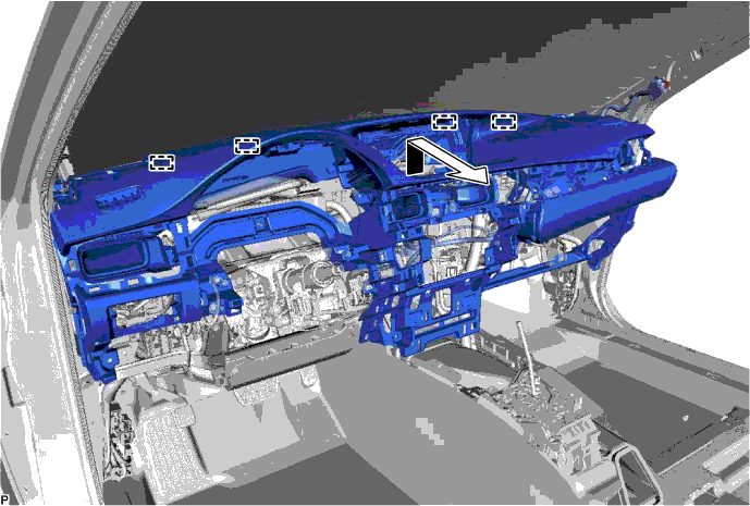
REMOVE INSTRUMENT PANEL SAFETY PAD ASSEMBLY
-
for LHD:
-
Disconnect each connector.
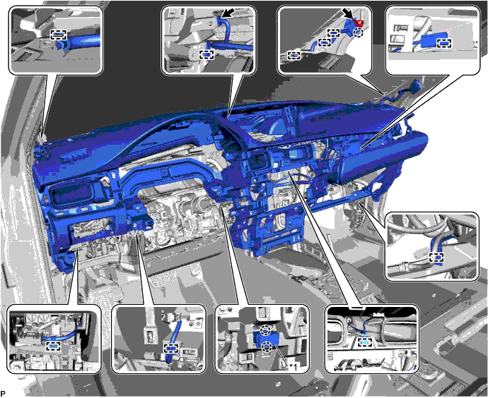
Text in Illustration *1 Cooler (Room Temp. Sensor) Thermistor - - -
Disengage the claw and each clamp.
-
Disengage the 2 claws to disconnect the cooler (room temp. sensor) thermistor.
-
-
for RHD:
-
Disconnect each connector.
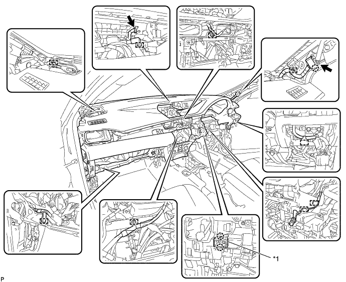
Text in Illustration *1 Cooler (Room Temp. Sensor) Thermistor - - -
Disengage the claw and each clamp.
-
Disengage the 2 claws to disconnect the cooler (room temp. sensor) thermistor.
-
-
Remove the 2 bolts <A>.
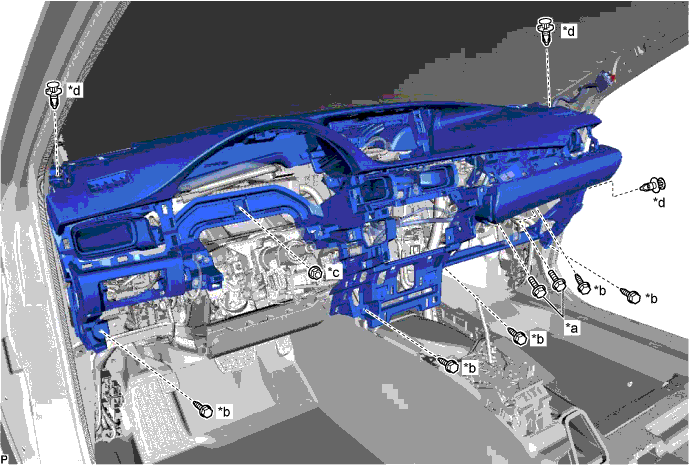
Text in Illustration *a Bolt <A> *b Bolt <C> *c Nut <F> *d Clip -
Remove the 5 bolts <C> and nut <F>.
-
Remove the 3 clips.
-
Disengage the 4 guides and remove the instrument panel safety pad assembly as shown in the illustration.
Note
-
Do not damage the instrument panel safety pad assembly.
-
Do not allow the wire harnesses to interfere with the surrounding parts.
-
-