CONDENSER INSTALLATION

-
INSTALL COOLER CONDENSER ASSEMBLY
-
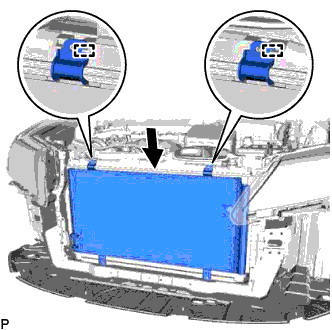
Engage the 2 guides as shown in the illustration.
-
Install the cooler condenser assembly with the 4 bolts.
- Torque:
- 5.0 N*m { 51 kgf*cm, 44 in.*lbf }
Tech Tips
If the cooler condenser assembly is replaced with a new one, add compressor oil to the new cooler condenser assembly.
Capacity 40 cc (1.4 fl. oz.) Compressor oil ND-8 or equivalent
-
-
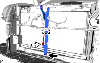
CONNECT AIR CONDITIONER TUBE AND ACCESSORY ASSEMBLY
-
Remove the vinyl tape from the tube and the connecting part of the cooler condenser assembly.
-
Sufficiently apply compressor oil to a new O-ring and the fitting surface of the tube joint.
Compressor oil ND-OIL 8 or equivalent -
Install the O-ring to the air conditioning tube and accessory assembly.
-
Install the air conditioning tube and accessory assembly to the cooler condenser assembly with the bolt.
- Torque:
- 9.8 N*m { 100 kgf*cm, 87 in.*lbf }
-
-
CONNECT NO. 1 COOLER REFRIGERANT DISCHARGE HOSE
-
Remove the vinyl tape from the pipe and the connecting part of the cooler condenser assembly.
-
Sufficiently apply compressor oil to a new O-ring and the fitting surface of the hose joint.
Compressor oil ND-OIL 8 or equivalent -
Install the O-ring to the No. 1 cooler refrigerant discharge hose.
-
Install the No. 1 cooler refrigerant discharge hose to the cooler condenser assembly with the bolt.
- Torque:
- 9.8 N*m { 100 kgf*cm, 87 in.*lbf }
-
-
INSTALL RADIATOR SIDE DEFLECTOR LH
-
Engage the guide and 3 claws to install the radiator side deflector LH.
-
-
INSTALL RADIATOR SIDE DEFLECTOR RH
-
Engage the guide and 3 claws to install the radiator side deflector RH.
-
-
INSTALL HOOD LOCK SUPPORT SUB-ASSEMBLY
-
Install the hood lock support sub-assembly with the bolt.
-
Engage the clamp.
-
Connect the connector.
-
-
INSTALL UPPER RADIATOR SUPPORT (for 2AR-FE)
-
Install the 2 radiator support cushions to the radiator assembly.
-
Install the upper radiator support with the 5 bolts and connect the hood lock control cable clamp to the upper radiator support.
- Torque:
- 13 N*m { 127 kgf*cm, 9 ft.*lbf }
-
Connect the 3 connectors.
-
-
INSTALL UPPER RADIATOR SUPPORT (for 2GR-FE)
-
Install the 2 radiator support cushions to the radiator assembly.
-
Install the upper radiator support with the 5 bolts and connect the hood lock control cable clamp to the upper radiator support.
- Torque:
- 13 N*m { 127 kgf*cm, 9 ft.*lbf }
-
Connect the 3 connectors.
-
-
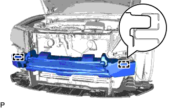
INSTALL FRONT BUMPER REINFORCEMENT SUB-ASSEMBLY
-
Install the front bumper reinforcement sub-assembly with the 6 bolts.
- Torque:
- 61 N*m { 622 kgf*cm, 45 ft.*lbf }
-
Engage the 6 clamps.
-
-
INSTALL FRONT BUMPER ENERGY ABSORBER
-
Engage the 2 guides to install the front bumper energy absorber.
-
-
INSTALL HOOD LOCK ASSEMBLY
-
for LHD:
-
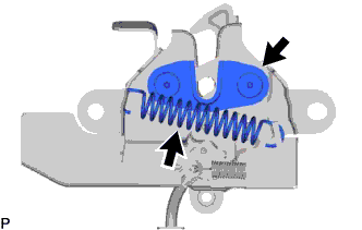
Apply MP grease to the sliding areas of the lock.
-
-
for RHD:
-
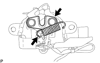
Apply MP grease to the sliding areas of the lock.
-
-
Connect the hood lock control cable assembly.
-
Install the hood lock assembly with the 3 bolts.
- Torque:
- 8.0 N*m { 82 kgf*cm, 71 in.*lbf }
-
Engage the clamp.
-
Connect the connector.
-
-
INSTALL MILLIMETER WAVE RADAR SENSOR ASSEMBLY (w/ Dynamic Radar Cruise Control System)
-
INSTALL INLET AIR CLEANER ASSEMBLY (for 2AR-FE)
-
Install the inlet air cleaner assembly with the 2 bolts.
- Torque:
- 8.0 N*m { 82 kgf*cm, 71 in.*lbf }
-
-
INSTALL INLET NO. 1 AIR CLEANER (for 2GR-FE)
-
Install the inlet No. 1 air cleaner to the intake air resonator sub-assembly.
-
Engage the pin to the radiator support.
-
-
INSTALL INLET NO. 2 AIR CLEANER (for 2GR-FE)
-
Install the inlet No. 2 air cleaner to the air cleaner case sub-assembly with the 2 bolts.
- Torque:
- 8.0 N*m { 82 kgf*cm, 71 in.*lbf }
-
Connect the 2 wire harness clamps and vacuum hose clamp.
-
-
INSTALL FRONT BUMPER ASSEMBLY
-
CONNECT CABLE TO NEGATIVE BATTERY TERMINAL
Note
When disconnecting the cable, some systems need to be initialized after the cable is reconnected Click here.
-
CHARGE AIR CONDITIONING SYSTEM WITH REFRIGERANT
-
Perform vacuum purging using a vacuum pump or appropriate equipment.
-
Charge the air conditioning system with refrigerant.
Refrigerant type HFC-134a (R134a) 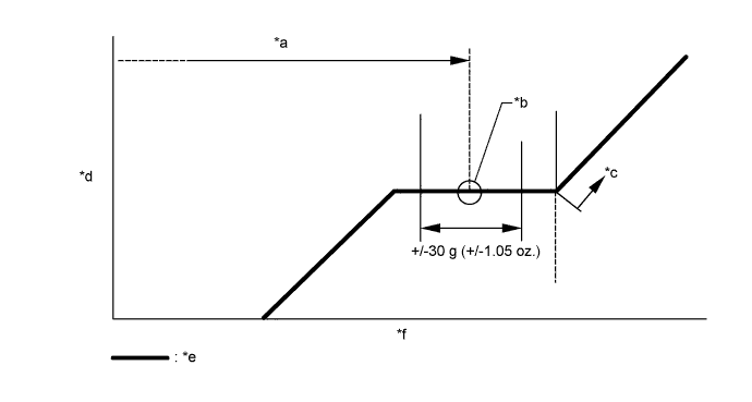
Text in Illustration *a Standard charge amount *b Mean value in proper range *c Overcharged *d High pressure *e Sub-cool system *f Refrigerant amount Standard charge amount 470 to 530 g (16.6 to 18.6 oz.) - SST
- 09985-20010 ( 09985-02010, 09985-02050, 09985-02060, 09985-02070, 09985-02080, 09985-02090, 09985-02110, 09985-02130, 09985-02140, 09985-02150 )
Note
-
Do not turn the A/C switch on before charging the air conditioning system with refrigerant. Doing so may cause the compressor to work without refrigerant, resulting in overheating of the compressor.
-
The refrigerant amount should be checked by quantity (weight).
-
The graph above is shown for reference only.
Tech Tips
Ensure that sufficient refrigerant is available to recharge the system when using a refrigerant recovery unit. Refrigerant recovery units are not always able to recover 100% of the refrigerant from an air conditioning system.
-
-
WARM UP ENGINE
-
Keep the A/C switch on for at least 2 minutes to warm up the compressor.
Note
To prevent damage to the compressor, be sure to warm up the compressor when turning the air conditioning on after removing and installing air conditioning system lines (including the compressor).
-
-
INSPECT FOR REFRIGERANT LEAK
-
After recharging the air conditioning system with refrigerant, check for refrigerant leaks using a halogen leak detector.
-
Carry out the test under the following conditions:
-
Turn the engine switch off.
-
Measure the pressure to make sure that there is some refrigerant remaining in the air conditioning system.
Pressure when the compressor is off: approx. 392 to 588 kPa (3.9 to 5.9 kgf/cm2, 57 to 85 psi)
-
Ensure good ventilation (the halogen leak detector may react to volatile gases which are not refrigerant, such as gasoline vapor and exhaust gas).
-
Repeat the inspection 2 or 3 times.
-
-
Remove the front outer cowl top panel sub-assembly Click here for LHD or Click here for RHD).
-
Remove the front bumper assembly Click here.
-
Remove the radiator side deflector RH Click here.
-
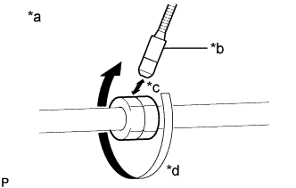
Text in Illustration *a Check for leaks *b Halogen Leak Detector Sensor *c Distance between Sensor and Joint to be Checked:
10 mm or less
*d Halogen Leak Detector Sensor Moving Speed:
25 to 50 mm/sec.
How to check for refrigerant leaks in pipe joints:
Note
Gas leaking from a joint can be dissipated by even the slightest breeze. Move the halogen leak detector sensor 360° around each joint instead of keeping it in one spot when checking.
-
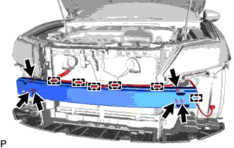
Using a halogen leak detector, check for refrigerant leaks at the pipe joints shown in the illustration.
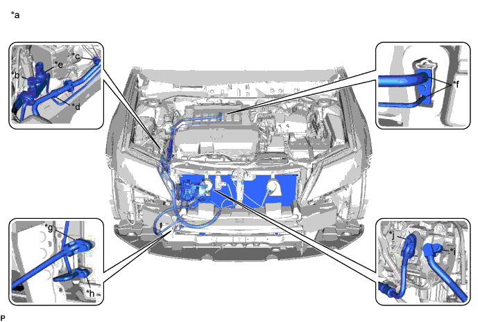
Text in Illustration *a Area to be Checked *b Service Valve (High) *c Service Valve (Low) *d Pipe Joint *e Air Conditioner Pressure Sensor Joint *f Cooler Expansion Valve Joint *g Condenser Joint (Inlet) *h Condenser Joint (Outlet) *i Compressor Joint (Inlet) *j Compressor Joint (Outlet) Tech Tips
-
After the blower motor has stopped, leave the cooling unit for more than 15 minutes.
-
Disconnect the pressure sensor connector and leave it for approximately 20 minutes.
-
When checking for leaks, the presence of oily dirt at a joint can indicate a leak.
Standard There are no refrigerant leaks from the joints. If refrigerant is leaking, disconnect the leaking joint and visually check for the cause, such as the presence of foreign matter.
-
-
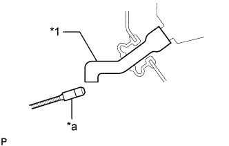
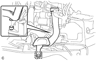
Text in Illustration *1 Drain Cooler Hose *a Halogen Leak Detector Bring the halogen leak detector sensor close to the drain cooler hose with the detector turned off, and then turn the detector on.
Note
Keep water away from the halogen leak detector to prevent malfunction.
Tech Tips
-
After the blower motor has stopped, leave the cooling unit for more than 15 minutes.
-
When bringing the halogen leak detector sensor close to the drain cooler hose, make sure that the halogen leak detector does not react to volatile gases. If it is not possible to avoid interference from volatile gases, the vehicle should be lifted up to allow checking for leaks.
Standard Refrigerant is not leaking from the drain cooler hose. If refrigerant is leaking, check for refrigerant leaks from the No. 1 cooler evaporator sub-assembly.
-
-
Remove the blower motor with fan sub-assembly Click here.
-
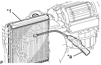
Text in Illustration *1 No. 1 Cooler Evaporator Sub-assembly *a Halogen Leak Detector Insert the halogen leak detector sensor into the air conditioning unit assembly, bring the sensor close to the No. 1 cooler evaporator sub-assembly and check for refrigerant leaks.
Tech Tips
After the blower motor has stopped, leave the cooling unit for more than 15 minutes.
Standard Refrigerant is not leaking from the No. 1 cooler evaporator sub-assembly. If refrigerant is leaking, disconnect the leaking joint and visually check for the cause, such as the presence of foreign matter.
-
Install the blower motor with fan sub-assembly Click here.
-
Install the radiator side deflector RH Click here.
-
Install the front bumper assembly Click here.
-
Install the front outer cowl top panel sub-assembly Click here for LHD or Click here for RHD).
-
-
ADJUST HOOD SUB-ASSEMBLY