COMPRESSOR (for 2GR-FE) INSPECTION

-
INSPECT COOLER COMPRESSOR ASSEMBLY (A/C LOCK SENSOR)
-
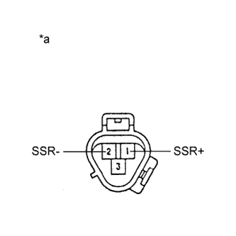
Text in Illustration *a Component without harness connected
(Cooler Compressor Assembly (A/C Lock Sensor))
Measure the resistance according to the value(s) in the table below.
Standard Resistance Tester Connection Condition Specified Condition 1 (SSR+) - 2 (SSR-) 20°C (68°F) 160 to 320 Ω If the resistance is not as specified, replace the cooler compressor assembly.
-
-
INSPECT COOLER COMPRESSOR ASSEMBLY (COMPRESSOR SOLENOID)
-
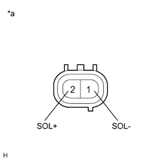
Text in Illustration *a Component without harness connected
(Cooler Compressor Assembly (Compressor Solenoid))
Measure the resistance according to the value(s) in the table below.
Standard Resistance Tester Connection Condition Specified Condition 1 (SOL-) - 2 (SOL+) 20°C (68°F) 10.1 to 11.1 Ω If the resistance is not as specified, replace the cooler compressor assembly.
-
-
INSPECT COOLER COMPRESSOR ASSEMBLY
-
Disconnect the D65 cooler compressor assembly connector.
-
Disconnect the a2 magnetic clutch assembly connector.
-
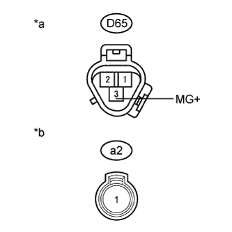
Text in Illustration *a Component without harness connected
(Cooler Compressor Assembly)
*b Component without harness connected
(Magnetic Clutch Assembly)
Measure the resistance according to the value(s) in the table below.
Standard Resistance Tester Connection Condition Specified Condition D65-3 (MG+) - a2-1 Always Below 1 Ω D65-3 (MG+) - Body ground Always 10 kΩ or higher If the resistance is not as specified, replace the cooler compressor assembly.
-
-
INSPECT MAGNET CLUTCH ASSEMBLY
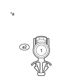
Text in Illustration *a Component without harness connected
(Magnetic Clutch Assembly)
-
Measure the resistance according to the value(s) in the table below.
Standard Resistance Tester Connection Condition Specified Condition a2-1 - Body ground 20°C (68°F) 3.8 to 4.2 Ω If the resistance is not as specified, replace the magnetic clutch assembly.
-
When connector terminal a2-1 is connected to the positive (+) battery terminal, check that the following occurs: 1) the magnetic clutch operating sound can be heard, and 2) the magnetic clutch hub and rotor lock.
OK 1): The magnetic clutch operating sound can be heard. 2): The magnetic clutch hub and rotor lock.
-
If the result is not as specified, replace the magnetic clutch assembly
-
-