AIR CONDITIONING UNIT INSTALLATION

-
INSTALL DRAIN COOLER HOSE
-
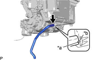
Text in Illustration *a Hose Notch *b Rib Align the hose notch and rib as shown in the illustration and install the drain cooler hose.
-
-
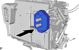
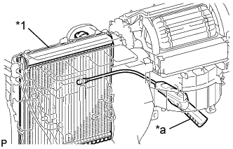
INSTALL ASPIRATOR PIPE
-
Engage the 2 claws to install the aspirator pipe.
-
-
INSTALL COOLER THERMISTOR HOSE
-
Install the cooler thermistor hose.
-
Engage the clamp.
-
-
INSTALL HEATER PACKING
-
Install the heater packing as shown in the illustration.
-
-
INSTALL NO. 4 AIR DUCT SUB-ASSEMBLY (for RHD)
-
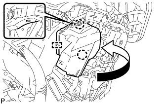
Engage the guide and 2 claws to install the No. 4 air duct sub-assembly as shown in the illustration.
-
-
INSTALL NO. 1 AIR DUCT SUB-ASSEMBLY
-

Engage the guide and 2 claws to install the No. 1 air duct sub-assembly as shown in the illustration.
-
-
INSTALL NO. 6 HEATER TO REGISTER DUCT ASSEMBLY
-
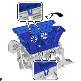
Engage the 2 guides and 2 claws to install the No. 6 heater to register duct assembly as shown in the illustration.
-
-
INSTALL AIR CONDITIONING HARNESS ASSEMBLY
-
Engage each clamp to install the air conditioning harness assembly.
-
Connect each connector.
-
-
INSTALL BLOWER ASSEMBLY
for LHD: Click here
for RHD: Click here
-
INSTALL AIR CONDITIONING UNIT ASSEMBLY
-
Install the air conditioning unit assembly to the instrument panel reinforcement assembly with the 3 bolts.
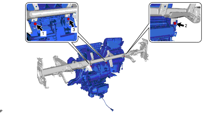
- Torque:
- 9.8 N*m { 100 kgf*cm, 87 in.*lbf }
Note
Tighten the bolts in the order shown in the illustration to install the air conditioning unit assembly.
-
-
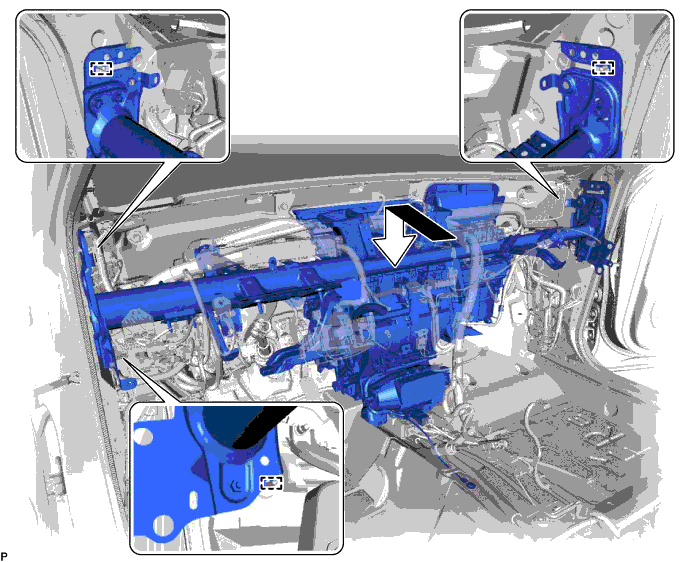
INSTALL INSTRUMENT PANEL REINFORCEMENT ASSEMBLY WITH AIR CONDITIONING UNIT
Note
-
Be sure to support the air conditioning unit assembly when installing it because failure to do so may cause the bracket of the air conditioning unit assembly to break.
-
When installing the air conditioning unit, eliminate static electricity by touching the vehicle body to prevent the components from being damaged.
-
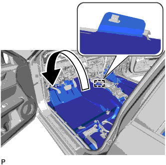
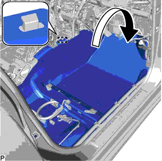
Engage the 3 guides and temporarily install the instrument panel reinforcement assembly with air conditioning unit as shown in the illustration.
-
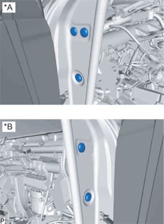
Install the instrument panel reinforcement assembly with the 3 bolts <A> and 2 new bolts <B> in the order shown in the illustration.
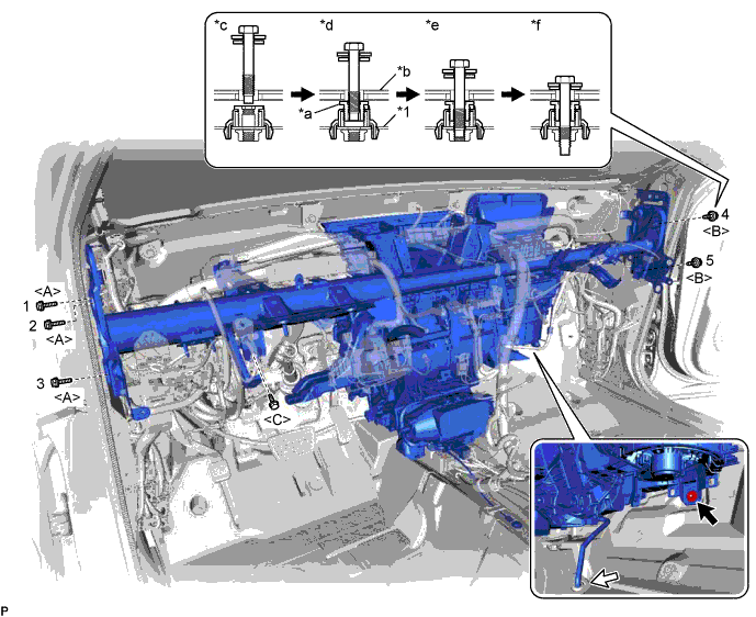
Text in Illustration *1 Instrument Panel Reinforcement Assembly - - *a Movable Collar *b Body *c Step 1 *d Step 2 *e Step 3 *f Step 4 - Torque:
- 20 N*m { 204 kgf*cm, 15 ft.*lbf }
Note
Tighten the bolts in the order shown in the illustration to install the reinforcement assembly.
-
Install the bolt <C>.
- Torque:
- 15 N*m { 153 kgf*cm, 11 ft.*lbf }
-
Install the instrument panel reinforcement assembly with air conditioning unit with the nut.
- Torque:
- 9.8 N*m { 100 kgf*cm, 87 in.*lbf }
-
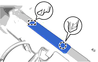
Pass the drain cooler hose through the vehicle securely.
Note
Connect the drain cooler hose firmly to prevent water leaks.
-
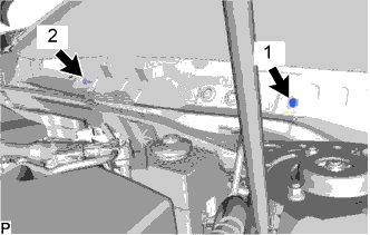
Install the 2 bolts.
- Torque:
- 9.8 N*m { 100 kgf*cm, 87 in.*lbf }
Note
Tighten the bolts in the order shown in the illustration.
-
Install the 2 hole plugs.
-
for LHD:
-
Engage each clamp.
-
Connect the connector.
-
Connect the 4 earth wires with the 4 bolts.
- Torque:
- 8.4 N*m { 86 kgf*cm, 74 in.*lbf }
-
Connect the protector with the nut.
- Torque:
- 8.0 N*m { 82 kgf*cm, 71 in.*lbf }
-
Connect the connector holder with the 2 nuts.
- Torque:
- 8.0 N*m { 82 kgf*cm, 71 in.*lbf }
-
-
for RHD:
-
Engage each clamp.
-
Connect the connector.
-
Connect the 4 earth wires with the 4 bolts.
- Torque:
- 8.4 N*m { 86 kgf*cm, 74 in.*lbf }
-
Connect the connector holder with the 2 nuts.
- Torque:
- 8.0 N*m { 82 kgf*cm, 71 in.*lbf }
-
-
Engage the claw to connect the airbag connector as shown in the illustration.
-
Text in Illustration *a Retainer Engage the 2 claws to lock the retainer as shown in the illustration.
-
w/ PTC Heater:
-
Connect the connector.
-
Install the bolt.
- Torque:
- 20 N*m { 199 kgf*cm, 14 ft.*lbf }
-
for U660E Automatic Transmission / Transaxle:
-
Install the shift lever support Click here.
-
Install the lower shift lever assembly Click here.
-
-
for U760E Automatic Transmission / Transaxle:
-
Install the shift lever support Click here.
-
Install the lower shift lever assembly Click here.
-
-
-
Engage each clamp.
Text in Illustration *1 Airbag Sensor Assembly - - -
Connect each connector.
-
Connect the connector to the airbag sensor assembly as shown in the illustration.
Note
When connecting any airbag connector, take care not to damage the airbag wire harness.
-
Engage the 3 claws to close the 3 clamps as shown in the illustration.
-
w/ Telematics Transceiver:
-
Engage each clamp.
-
-
Engage each clamp.
-
-
INSTALL INSTRUMENT PANEL SAFETY PAD CAP
-
Text in Illustration *A for LH Side *B for RH Side Install 5 new instrument panel safety pad caps.
-
-
INSTALL NO. 1 HEATER TO REGISTER DUCT
-
Install the No. 1 heater to register duct with the 3 clips.
-
Engage the clamp.
-
-
INSTALL NO. 2 INSTRUMENT PANEL BRACE SUB-ASSEMBLY
-
Install the No. 2 instrument panel brace sub-assembly with the bolt and 2 nuts.
- Torque:
- 20 N*m { 204 kgf*cm, 15 ft.*lbf }
-
Install the screw.
-
Engage each clamp.
-
Connect the connector.
-
Connect the earth wire with the bolt.
- Torque:
- 8.4 N*m { 86 kgf*cm, 74 in.*lbf }
-
-
INSTALL NO. 1 INSTRUMENT PANEL BRACE SUB-ASSEMBLY
-
Install the No. 1 instrument panel brace sub-assembly with the bolt and 2 nuts.
- Torque:
- 20 N*m { 204 kgf*cm, 15 ft.*lbf }
-
Install the screw.
-
Engage the clamp.
-
Connect the connector.
-
-
INSTALL COOLER (ROOM TEMP. SENSOR) THERMISTOR
-
Connect the cooler thermistor hose and connector to install the cooler (room temp. sensor) thermistor.
-
-
INSTALL NO. 1 CONSOLE BOX DUCT
-
Install the No. 1 console box duct with the clip.
-
-
INSTALL NO. 1 CONSOLE BOX MOUNTING BRACKET (w/ PTC Heater)
for U660E Automatic Transmission / Transaxle: Click here
for U760E Automatic Transmission / Transaxle: Click here
-
INSTALL FLOOR CARPET BRACKET LH
-
Engage the 2 guides.
-
Install the floor carpet bracket LH with the 2 clips.
-
-
INSTALL REAR NO. 2 AIR DUCT
-
Engage the 2 claws to install the rear No. 2 air duct.
-
-
INSTALL REAR AIR DUCT GUIDE LH
-
Engage the 4 claws to install the rear air duct guide LH.
-
Engage the guide to install the floor carpet to the original position as shown in the illustration.
-
-
INSTALL FLOOR CARPET BRACKET RH
-
Engage the 2 guides.
-
Install the floor carpet bracket RH with the 2 clips.
-
-
INSTALL REAR NO. 1 AIR DUCT
-
Engage the 2 claws to install the rear No. 1 air duct.
-
-
INSTALL REAR AIR DUCT GUIDE RH
-
Engage the 4 claws to install the rear air duct guide RH.
-
Engage the guide to install the floor carpet to the original position as shown in the illustration.
-
-
INSTALL FRONT FLOOR CAUTION PLATE COVER
-
Engage the guide and claw to install the front floor caution plate cover.
-
-
INSTALL FLOOR CARPET HOOK
-
Engage the 6 clamps to install the 6 floor carpet hooks.
-
Engage the 6 guides.
-
-
INSTALL AIR CONDITIONING AMPLIFIER ASSEMBLY
-
Engage the 2 guides to temporarily install the air conditioning amplifier assembly.
-
Install the air conditioning amplifier assembly with the 2 screws.
-
Connect the 3 connectors.
-
-
INSTALL ECU INTEGRATION BOX RH
for LHD: Click here
for RHD: Click here
-
INSTALL WIRING HARNESS CLAMP BRACKET (for RHD)
-
Engage the claw.
-
Install the wiring harness clamp bracket with the nut.
- Torque:
- 8.0 N*m { 82 kgf*cm, 71 in.*lbf }
-
-
INSTALL INSTRUMENT PANEL JUNCTION BLOCK ASSEMBLY WITH MAIN BODY ECU
-
for LHD:
-
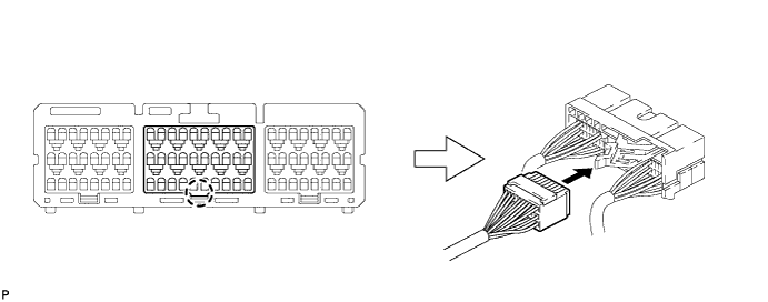
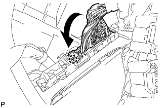
Engage the claw to connect the connector as shown in the illustration.
Note
Be sure to engage the connector securely.
-
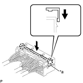
Engage the claw to lock the connector lock as shown in the illustration.
-
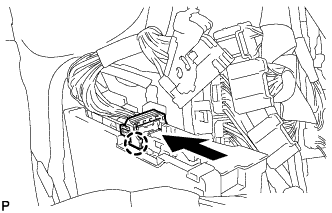
Engage the claw to connect the connector as shown in the illustration.
Note
Be sure to engage the connector securely.
-
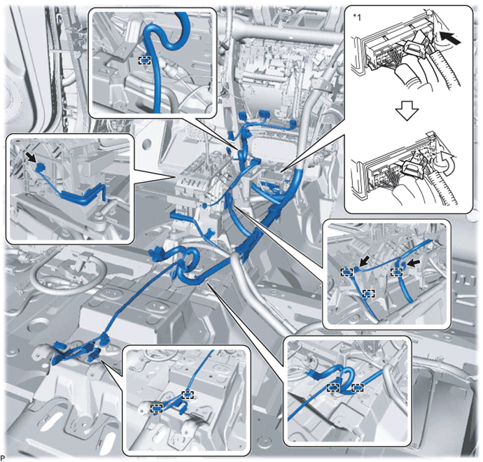
Install the instrument panel junction block assembly with main body ECU with the bolt and 2 nuts.
- Torque:
- 8.0 N*m { 82 kgf*cm, 71 in.*lbf }
-
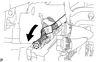
Engage the claw to connect the connector as shown in the illustration.
Note
Be sure to engage the connector securely.
-
Engage the claw to connect the connector as shown in the illustration.
Note
Be sure to engage the connector securely.
-
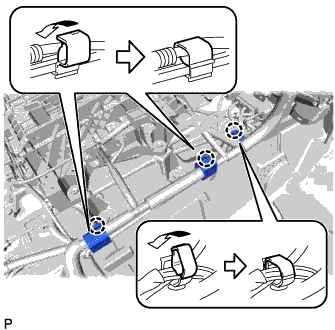
Connect each connector.
-
-
for RHD:
-
Engage the claw to connect the connector as shown in the illustration.
Note
Be sure to engage the connector securely.
-
Engage the claw to lock the connector lock as shown in the illustration.
-
Engage the claw to connect the connector as shown in the illustration.
Note
Be sure to engage the connector securely.
-
Install the instrument panel junction block assembly with main body ECU with the bolt and nut.
- Torque:
- 8.0 N*m { 82 kgf*cm, 71 in.*lbf }
-
Engage the claw to connect the connector as shown in the illustration.
Note
Be sure to engage the connector securely.
-
Engage the claw to connect the connector as shown in the illustration.
Note
Be sure to engage the connector securely.
-
Connect each connector.
-
-
-
INSTALL DRIVING SUPPORT ECU ASSEMBLY (w/ Dynamic Radar Cruise Control System)
for RHD: Click here
-
INSTALL SEAT BELT CONTROL ECU (w/ Pre-crash Safety System)
-
Install the seat belt control ECU with the bolt.
- Torque:
- 8.0 N*m { 82 kgf*cm, 71 in.*lbf }
-
Connect each connector.
-
-
INSTALL WINDSHIELD WIPER RELAY ASSEMBLY (w/ Rain Sensor)
-
Connect the connector.
-
Install the windshield wiper relay assembly with the nut.
-
-
INSTALL STEERING POST ASSEMBLY
-
INSTALL INSTRUMENT PANEL SAFETY PAD ASSEMBLY
-
INSTALL STEREO COMPONENT AMPLIFIER ASSEMBLY WITH BRACKET
-
Engage the 2 guides to temporarily install the stereo component amplifier assembly with bracket.
-
Install the stereo component amplifier assembly with bracket with the bolt.
-
Connect each connector.
-
-
INSTALL AUDIO AMPLIFIER COVER
-
Engage the 2 claws to temporarily install the audio amplifier cover.
-
Install the audio amplifier cover with the clip.
-
-
INSTALL FRONT SEAT ASSEMBLY LH
-
INSTALL TELEMATICS TRANSCEIVER WITH MAYDAY BATTERY (w/ Telematics Transceiver)
-
Connect each connector.
-
Engage the 2 guides to the vehicle body to temporarily install the telematics transceiver with mayday battery.
-
Install the telematics transceiver with back-up battery with the bolt.
-
-
INSTALL AUDIO AMPLIFIER COVER (w/ Telematics Transceiver)
-
Install the audio amplifier cover with the 2 clips.
-
-
INSTALL FRONT SEAT ASSEMBLY RH
Tech Tips
Use the same procedure as for the LH side.
-
CONNECT AIR CONDITIONER TUBE AND ACCESSORY ASSEMBLY
-
Remove the vinyl tape from the air conditioning tube and accessory assembly.
-
Sufficiently apply compressor oil to a new O-ring and fitting surface of the air conditioning tube and accessory assembly.
Compressor oil ND-OIL 8 or equivalent -
Install the O-ring to the air conditioning tube and accessory assembly.
-
Install the air conditioning tube and accessory assembly.
-
-
CONNECT SUCTION PIPE SUB-ASSEMBLY
-
Remove the vinyl tape from the suction pipe sub-assembly.
-
Sufficiently apply compressor oil to a new O-ring and the fitting surface of the suction pipe sub-assembly.
Compressor oil ND-OIL 8 or equivalent -
Install the O-ring to the suction pipe sub-assembly.
-
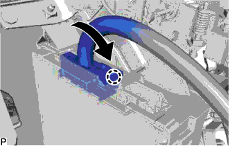
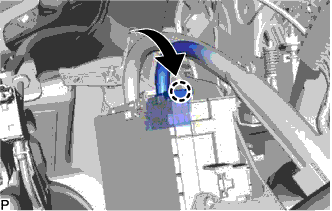
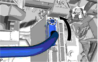
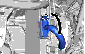
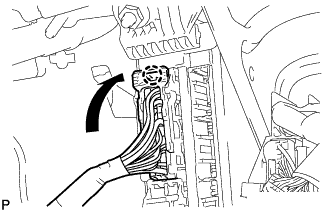
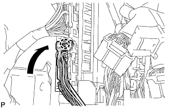
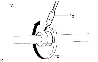
Connect the suction pipe sub-assembly.
-
Rotate the hook connector in the direction indicated by the arrow in the illustration.
-
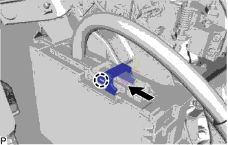
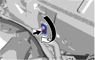
Insert the pipe joint into the fitting hole securely and tighten the bolt.
- Torque:
- 9.8 N*m { 100 kgf*cm, 87 in.*lbf }
-
-
CONNECT HEATER INLET WATER HOSE
-
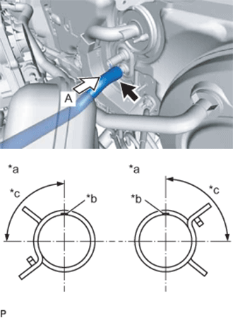
Text in Illustration *a View A *b for 2GR-FE:
Marking (Brown)
for 2AR-FE:
Marking (Yellow)
*c Clip installation angle (75 to 105°) Connect the heater inlet water hose with the marking facing up and engage the clip within the area shown in the illustration.
Note
Do not apply excessive force to the heater inlet water hose.
-
-
CONNECT HEATER OUTLET WATER HOSE
-
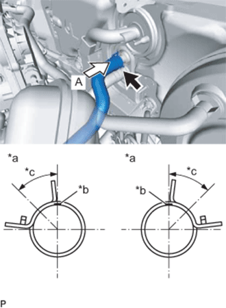
Text in Illustration *a View A *b for 2GR-FE without ATF Warmer:
Marking (Pink)
for 2GR-FE with ATF Warmer:
Marking (Green)
for 2AR-FE:
Marking (Red)
*c Clip installation angle (30 to 60°) Connect the heater outlet water hose with the marking facing up and engage the clip within the area shown in the illustration.
Note
Do not apply excessive force to the heater outlet water hose.
-
-
INSTALL FRONT OUTER COWL TOP PANEL SUB-ASSEMBLY
for LHD: Click here
for RHD: Click here
-
INSTALL WINDSHIELD WIPER MOTOR AND LINK ASSEMBLY
-
ADD ENGINE COOLANT (for 2AR-FE)
-
Tighten the radiator drain cock plug by hand.
-
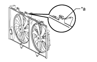
Text in Illustration *a Code Mark Check the code mark on the fan shroud.
-
Slowly fill the radiator assembly with TOYOTA Super Long Life Coolant (SLLC).
Specified capacity: Code Mark F and X 7.3 liters (7.7 US qts, 6.4 Imp. qts) Code Mark R 7.9 liters (8.3 US qts, 7.0 Imp. qts) Note
Never use water as a substitute for engine coolant.
Tech Tips
TOYOTA vehicles are filled with TOYOTA SLLC at the factory. In order to avoid damage to the engine cooling system and other technical problems, only use TOYOTA SLLC or similar high quality ethylene glycol based non-silicate, non-amine, non-nitrite, non-borate coolant with long-life hybrid organic acid technology (coolant with long-life hybrid organic acid technology is a combination of low phosphates and organic acids).
-
Slowly pour engine coolant into the radiator reserve tank assembly until it reaches the full line.
-
Squeeze the No. 1 and No. 2 radiator hoses several times by hand, and then check the level of the engine coolant.
If the engine coolant level is low, add engine coolant.
-
Install the radiator cap sub-assembly and reserve tank cap.
-
Bleed air from the cooling system.
Note
-
Before starting the engine, turn the A/C switch off.
-
Adjust the heater control to the maximum hot setting.
-
Adjust the blower speed to the low setting.
-
Warm up the engine until the thermostat opens. While the thermostat is open, circulate the engine coolant for several minutes.
Tech Tips
The thermostat open timing can be confirmed by squeezing the No. 2 radiator hose by hand, and sensing vibrations when the engine coolant starts to flow inside the No. 2 radiator hose.
-
Maintain the engine speed at 2500 to 3000 rpm.
-
Squeeze the No. 1 and No. 2 radiator hoses several times by hand to bleed air.
CAUTION:
When squeezing the No. 1 and No. 2 radiator hoses:
-
Wear protective gloves.
-
Be careful as the No. 1 and No. 2 radiator hoses are hot.
-
Keep your hands away from the cooling fans.
Note
-
Make sure that the radiator reserve tank assembly still has some engine coolant in it.
-
If the coolant temperature gauge indicates an excessive temperature, turn off the engine and let it cool.
-
If there is not enough engine coolant, the engine may overheat or be seriously damaged.
-
If the radiator reserve tank assembly does not have enough engine coolant, perform the following: 1) stop the engine, 2) wait until the engine coolant has cooled down, and 3) add engine coolant until the radiator reserve tank assembly is filled to the full line.
-
-
-
Stop the engine and wait until the engine coolant cools down.
-
Add engine coolant to the full line on the radiator reserve tank assembly.
-
-
ADD ENGINE COOLANT (for 2GR-FE)
-
Tighten the radiator drain cock plug by hand.
-
Tighten the cylinder block drain cock plug. (for Bank 1)
- Torque:
- 13 N*m { 130 kgf*cm, 9 ft.*lbf }
-
Tighten the cylinder block drain cock plug. (for Bank 2, w/ Cylinder Block Drain Cock Plug)
- Torque:
- 13 N*m { 130 kgf*cm, 9 ft.*lbf }
-
Loosen the air drain cock plug on the water inlet housing.
-
Add engine coolant to the radiator inlet opening until engine coolant overflows from the air drain cock hole. Then tighten the air drain cock plug to the water inlet housing.
- Torque:
- 13 N*m { 130 kgf*cm, 9 ft.*lbf }
-
Text in Illustration *a Code Mark Check the code mark on the fan shroud.
-
Slowly fill the radiator assembly with engine coolant.
Specified Capacity: Code Mark I and V 9.2 liters (9.7 US qts, 8.1 Imp. qts) Code Mark W 9.4 liters (9.9 US qts, 8.3 Imp. qts) Note
Do not substitute plain water for engine coolant.
Tech Tips
TOYOTA vehicles are filled with TOYOTA SLLC at the factory. In order to avoid damage to the engine cooling system and other technical problems, only use TOYOTA SLLC or similar high quality ethylene glycol based non-silicate, non-amine, non-nitrite, non-borate coolant with long-life hybrid organic acid technology (coolant with long-life hybrid organic acid technology is a combination of low phosphates and organic acids).
-
Slowly pour engine coolant into the radiator reserve tank assembly until it reaches the full line.
-
Squeeze the No. 1 radiator hose and No. 2 radiator hose several times by hand, and then check the level of the engine coolant.
If the engine coolant level is low, add engine coolant.
-
Install the radiator cap sub-assembly and reserve tank cap.
-
Bleed air from the cooling system.
Note
-
Before starting the engine, turn the A/C switch off.
-
Adjust the heater control to the maximum hot setting.
-
Adjust the blower speed to the low setting.
-
Warm up the engine until the thermostat opens. While the thermostat is open, circulate the engine coolant for several minutes.
Tech Tips
The thermostat open timing can be confirmed by squeezing the No. 2 radiator hose by hand, and sensing vibrations when the engine coolant starts to flow inside the No. 2 radiator hose.
-
Maintain the engine speed at 2500 to 3000 rpm.
-
Squeeze the No. 1 radiator hose and No. 2 radiator hose several times by hand to bleed air.
CAUTION:
When squeezing the No. 1 radiator hose and No. 2 radiator hose:
-
Wear protective gloves.
-
Be careful as the No. 1 radiator hose and No. 2 radiator hose are hot.
-
Keep your hands away from the fan and No. 2 fan.
Note
-
If the coolant temperature gauge indicates an excessive temperature, turn off the engine and let it cool.
-
Make sure that the radiator reserve tank assembly still has some engine coolant in it.
-
If the radiator reserve tank assembly does not have enough engine coolant, the engine may overheat or be seriously damaged.
-
If the radiator reserve tank assembly does not have enough engine coolant, perform the following: 1) stop the engine, 2) wait until the engine coolant has cooled down, and 3) add engine coolant until the radiator reserve tank assembly is filled to the full line.
-
-
-
Stop the engine, and wait until the engine coolant cools down.
-
Add engine coolant to the full line on the radiator reserve tank assembly.
-
-
INSPECT FOR COOLANT LEAK (for 2AR-FE)
Note
Before performing each inspection, turn the A/C switch off.
-
Fill the radiator assembly with engine coolant and attach a radiator cap tester.
-
Warm up the engine.
-
Using a radiator cap tester, increase the pressure inside the radiator assembly to 118 kPa (1.2 kgf/cm2, 17 psi), and check that the pressure does not drop.
If the pressure drops, check the hoses, radiator assembly and engine water pump assembly for leaks. If no external leaks are found, check the heater core, cylinder block and cylinder head.
-
-
INSPECT FOR COOLANT LEAK (for 2GR-FE)
CAUTION:
Do not remove the radiator cap sub-assembly while the engine and radiator are still hot. Pressurized, hot engine coolant and steam may be released and cause serious burns.
Note
Before performing each inspection, turn the A/C switch OFF.
-
Fill the radiator with engine coolant and attach a radiator cap tester.
-
Warm up the engine.
-
Using a radiator cap tester, increase the pressure inside the radiator to 118 kPa (1.2 kgf*cm, 17 psi), and check that the pressure does not drop.
If the pressure drops, check the hoses, radiator assembly and engine water pump assembly for leaks. If no external leaks are found, check the heater core, cylinder block and cylinder head.
-
-
CHARGE AIR CONDITIONING SYSTEM WITH REFRIGERANT
-
Perform vacuum purging using a vacuum pump or appropriate equipment.
-
Charge the air conditioning system with refrigerant.
Refrigerant type HFC-134a (R134a) 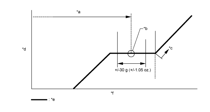
Text in Illustration *a Standard charge amount *b Mean value in proper range *c Overcharged *d High pressure *e Sub-cool system *f Refrigerant amount Standard charge amount 470 to 530 g (16.6 to 18.6 oz.) - SST
- 09985-20010 ( 09985-02010, 09985-02050, 09985-02060, 09985-02070, 09985-02080, 09985-02090, 09985-02110, 09985-02130, 09985-02140, 09985-02150 )
Note
-
Do not turn the A/C switch on before charging the air conditioning system with refrigerant. Doing so may cause the compressor to work without refrigerant, resulting in overheating of the compressor.
-
The refrigerant amount should be checked by quantity (weight).
-
The graph above is shown for reference only.
Tech Tips
Ensure that sufficient refrigerant is available to recharge the system when using a refrigerant recovery unit. Refrigerant recovery units are not always able to recover 100% of the refrigerant from an air conditioning system.
-
-
WARM UP ENGINE
-
Keep the A/C switch on for at least 2 minutes to warm up the compressor.
Note
To prevent damage to the compressor, be sure to warm up the compressor when turning the air conditioning on after removing and installing air conditioning system lines (including the compressor).
-
-
INSPECT FOR REFRIGERANT LEAK
-
After recharging the air conditioning system with refrigerant, check for refrigerant leaks using a halogen leak detector.
-
Carry out the test under the following conditions:
-
Turn the engine switch off.
-
Measure the pressure to make sure that there is some refrigerant remaining in the air conditioning system.
Pressure when the compressor is off: approx. 392 to 588 kPa (3.9 to 5.9 kgf/cm2, 57 to 85 psi)
-
Ensure good ventilation (the halogen leak detector may react to volatile gases which are not refrigerant, such as gasoline vapor and exhaust gas).
-
Repeat the inspection 2 or 3 times.
-
-
Remove the front outer cowl top panel sub-assembly Click here for LHD or Click here for RHD).
-
Remove the front bumper assembly Click here.
-
Remove the radiator side deflector RH Click here.
-
Text in Illustration *a Check for leaks *b Halogen Leak Detector Sensor *c Distance between Sensor and Joint to be Checked:
10 mm or less
*d Halogen Leak Detector Sensor Moving Speed:
25 to 50 mm/sec.
How to check for refrigerant leaks in pipe joints:
Note
Gas leaking from a joint can be dissipated by even the slightest breeze. Move the halogen leak detector sensor 360° around each joint instead of keeping it in one spot when checking.
-
Using a halogen leak detector, check for refrigerant leaks at the pipe joints shown in the illustration.
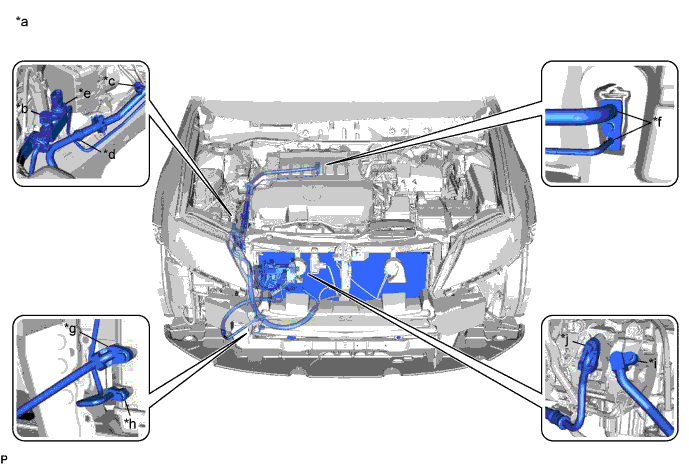
Text in Illustration *a Area to be Checked *b Service Valve (High) *c Service Valve (Low) *d Pipe Joint *e Air Conditioner Pressure Sensor Joint *f Cooler Expansion Valve Joint *g Condenser Joint (Inlet) *h Condenser Joint (Outlet) *i Compressor Joint (Inlet) *j Compressor Joint (Outlet) Tech Tips
-
After the blower motor has stopped, leave the cooling unit for more than 15 minutes.
-
Disconnect the pressure sensor connector and leave it for approximately 20 minutes.
-
When checking for leaks, the presence of oily dirt at a joint can indicate a leak.
Standard There are no refrigerant leaks from the joints. If refrigerant is leaking, disconnect the leaking joint and visually check for the cause, such as the presence of foreign matter.
-
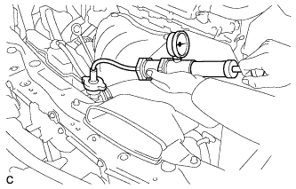
-
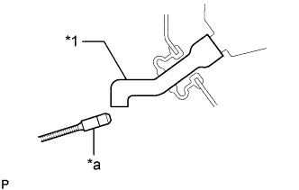
Text in Illustration *1 Drain Cooler Hose *a Halogen Leak Detector Bring the halogen leak detector sensor close to the drain cooler hose with the detector turned off, and then turn the detector on.
Note
Keep water away from the halogen leak detector to prevent malfunction.
Tech Tips
-
After the blower motor has stopped, leave the cooling unit for more than 15 minutes.
-
When bringing the halogen leak detector sensor close to the drain cooler hose, make sure that the halogen leak detector does not react to volatile gases. If it is not possible to avoid interference from volatile gases, the vehicle should be lifted up to allow checking for leaks.
Standard Refrigerant is not leaking from the drain cooler hose. If refrigerant is leaking, check for refrigerant leaks from the No. 1 cooler evaporator sub-assembly.
-
-
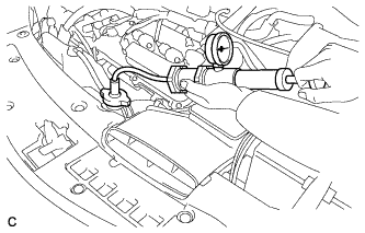
Remove the blower motor with fan sub-assembly Click here.
-
Text in Illustration *1 No. 1 Cooler Evaporator Sub-assembly *a Halogen Leak Detector Insert the halogen leak detector sensor into the air conditioning unit assembly, bring the sensor close to the No. 1 cooler evaporator sub-assembly and check for refrigerant leaks.
Tech Tips
After the blower motor has stopped, leave the cooling unit for more than 15 minutes.
Standard Refrigerant is not leaking from the No. 1 cooler evaporator sub-assembly. If refrigerant is leaking, disconnect the leaking joint and visually check for the cause, such as the presence of foreign matter.
-
Install the blower motor with fan sub-assembly Click here.
-
Install the radiator side deflector RH Click here.
-
Install the front bumper assembly Click here.
-
Install the front outer cowl top panel sub-assembly Click here for LHD or Click here for RHD).
-
-
INITIALIZE SERVO MOTOR
-
INSPECT SHIFT LEVER POSITION (w/ PTC Heater)
for U660E Automatic Transmission / Transaxle: Click here
for U760E Automatic Transmission / Transaxle: Click here