AIR CONDITIONING UNIT REMOVAL

Note
Make sure to select FACE mode before disconnecting the cable from the negative (-) battery terminal.
-
RECOVER REFRIGERANT FROM REFRIGERATION SYSTEM
-
Start the engine.
-
Operate the cooler compressor under the conditions shown below:
Item Condition Indicator Operating Time 3 minutes or more - Temperature setting Max cool - Blower speed High 
Engine Idling - A/C switch On 
This causes most of the compressor oil from the various components of the A/C system to collect in the A/C compressor.
Tech Tips
It is not necessary to operate the cooler compressor if the A/C does not operate because of compressor lock, etc.
-
Stop the engine.
-
Recover the refrigerant from the A/C system using a refrigerant recovery unit.
Tech Tips
Use the refrigerant recovery unit in accordance with the manufacturer's instruction manual.
-
-
REMOVE WINDSHIELD WIPER MOTOR AND LINK ASSEMBLY
-
REMOVE FRONT OUTER COWL TOP PANEL SUB-ASSEMBLY
for LHD: Click here
for RHD: Click here
-
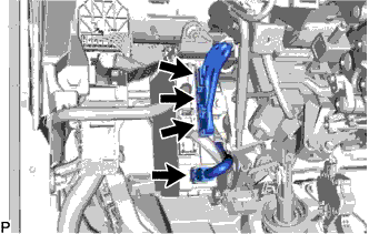
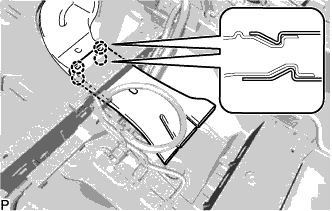
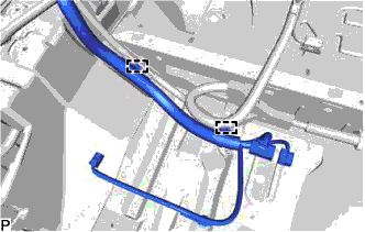
DISCONNECT HEATER OUTLET WATER HOSE
-
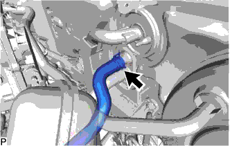
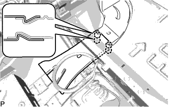
Using pliers, grip the claws of the clip and slide the clip to disconnect the heater outlet water hose.
Note
-
Do not apply excessive force to the heater outlet water hose.
-
Prepare a drain pan or cloth in case the coolant leaks.
-
-
-
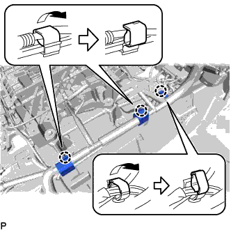
DISCONNECT HEATER INLET WATER HOSE
-
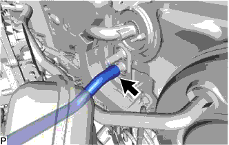
Using pliers, grip the claws of the clip and slide the clip to disconnect the heater inlet water hose.
Note
-
Do not apply excessive force to the heater inlet water hose.
-
Prepare a drain pan or cloth in case the coolant leaks.
-
-
-
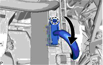
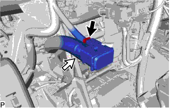
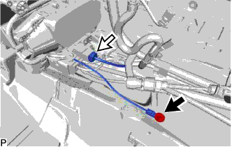
DISCONNECT SUCTION PIPE SUB-ASSEMBLY
-
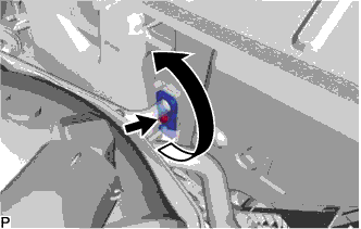
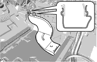
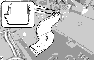
Remove the bolt and rotate the hook connector.
-
Disconnect the suction pipe sub-assembly.
-
Remove the O-ring from the suction pipe sub-assembly.
Note
Seal the openings of the disconnected parts using vinyl tape to prevent entry of moisture and foreign matter.
-
-
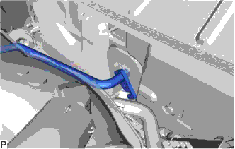
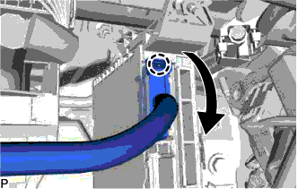
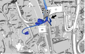
DISCONNECT AIR CONDITIONER TUBE AND ACCESSORY ASSEMBLY
-
Disconnect the air conditioner tube and accessory assembly.
-
Remove the O-ring from the air conditioner tube and accessory assembly.
Note
Seal the openings of the disconnected parts using vinyl tape to prevent entry of moisture and foreign matter.
-
-
REMOVE FRONT SEAT ASSEMBLY LH
-
REMOVE AUDIO AMPLIFIER COVER
-
Using a clip remover, remove the clip.
-
Disengage the 2 claws and remove the audio amplifier cover.
-
-
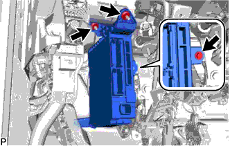
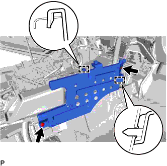
REMOVE STEREO COMPONENT AMPLIFIER ASSEMBLY WITH BRACKET
-
Disconnect each connector.
-
Remove the bolt.
-
Disengage the 2 guides and remove the stereo component amplifier assembly with bracket.
-
-
REMOVE FRONT SEAT ASSEMBLY RH
Tech Tips
Use the same procedure as for the LH side.
-
REMOVE AUDIO AMPLIFIER COVER (w/ Telematics Transceiver)
-
Using a clip remover, remove the 2 clips and audio amplifier cover.
-
-
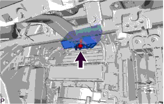
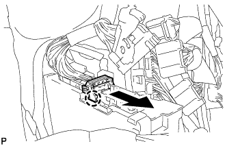
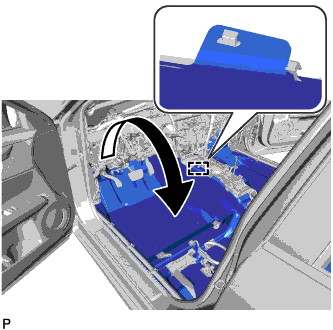
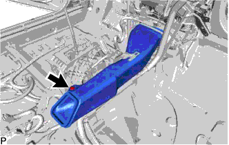
REMOVE TELEMATICS TRANSCEIVER WITH MAYDAY BATTERY (w/ Telematics Transceiver)
-
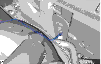
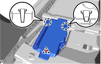
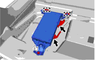
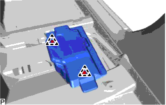
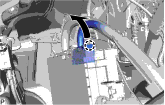
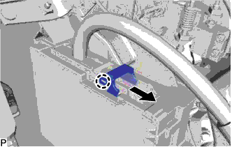
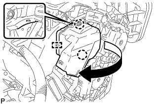
Remove the bolt and disengage the 2 guides.
-
Pull out the telematics transceiver with mayday battery in the direction indicated by the arrow shown in the illustration.
-
Disconnect each connector.
-
-
REMOVE INSTRUMENT PANEL SAFETY PAD ASSEMBLY
-
REMOVE STEERING POST ASSEMBLY
-
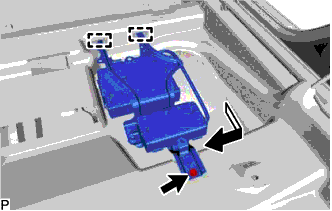
REMOVE WINDSHIELD WIPER RELAY ASSEMBLY (w/ Rain Sensor)
-
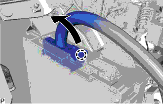
Remove the nut.
-
Disconnect the connector and remove the windshield wiper relay assembly.
-
-
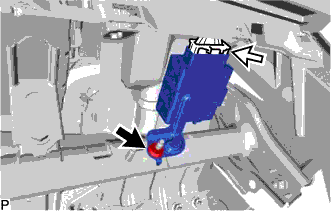
REMOVE DRIVING SUPPORT ECU ASSEMBLY (w/ Dynamic Radar Cruise Control System)
for RHD: Click here
-
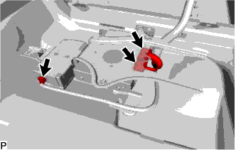
REMOVE SEAT BELT CONTROL ECU (w/ Pre-crash Safety System)
-
Disconnect each connector.
-
Remove the bolt and seat belt control ECU.
-
-
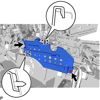
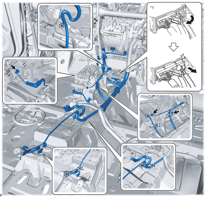
REMOVE INSTRUMENT PANEL JUNCTION BLOCK ASSEMBLY WITH MAIN BODY ECU
-
for LHD:
-
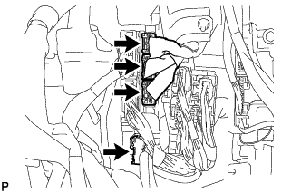
Disconnect each connector.
-
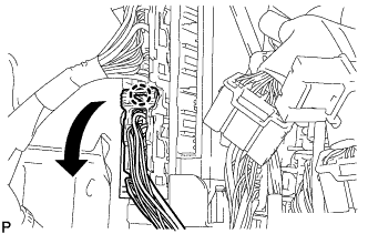
Disengage the claw and disconnect the connector as shown in the illustration.
-
Disengage the claw and disconnect the connector as shown in the illustration.
-
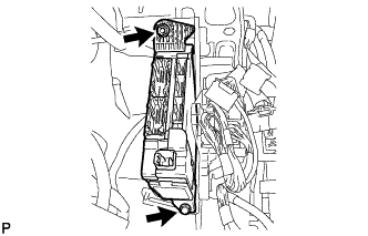
Remove the bolt and 2 nuts, and pull out the instrument panel junction block assembly with main body ECU.
-
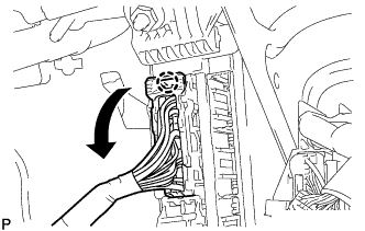
Disengage the claw and disconnect the connector as shown in the illustration.
-
Disengage the claw and release the connector lock as shown in the illustration.
-
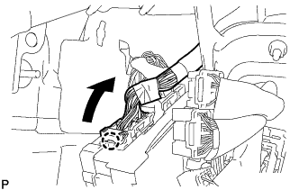
Disengage the claw and disconnect the connector as shown in the illustration to remove the instrument panel junction block assembly with main body ECU.
-
-
for RHD:
-
Disconnect each connector.
-
Disengage the claw and disconnect the connector as shown in the illustration.
-
Disengage the claw and disconnect the connector as shown in the illustration.
-
Remove the bolt and nut, and pull out the instrument panel junction block assembly with main body ECU.
-
Disengage the claw and disconnect the connector as shown in the illustration.
-
Disengage the claw and release the connector lock as shown in the illustration.
-
Disengage the claw and disconnect the connector as shown in the illustration to remove the instrument panel junction block assembly with main body ECU.
-
-
-
REMOVE WIRING HARNESS CLAMP BRACKET (for RHD)
-
Remove the nut.
-
Disengage the claw to remove the wiring harness clamp bracket.
-
-
REMOVE ECU INTEGRATION BOX RH
for LHD: Click here
for RHD: Click here
-
REMOVE AIR CONDITIONING AMPLIFIER ASSEMBLY
-
Disconnect the 3 connectors.
-
Remove the 2 screws.
-
Disengage the 2 guides and remove the air conditioning amplifier assembly.
-
-
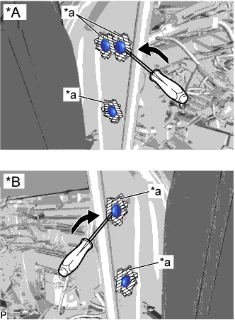
REMOVE FLOOR CARPET HOOK
-
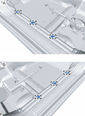
Text in Illustration *A for LH Side *B for RH Side Disengage the 6 guides.
-
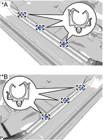
Text in Illustration *A for LH Side *B for RH Side Disengage the 6 clamps and remove the 6 floor carpet hooks.
-
-
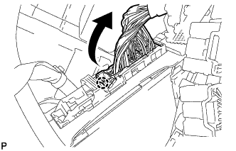
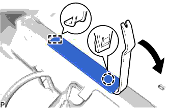
REMOVE REAR AIR DUCT GUIDE LH
-
Disengage the guide.
-
Turn back the floor carpet as shown in the illustration.
-
Disengage the 4 claws to remove the rear air duct guide LH.
-
-
REMOVE REAR NO. 2 AIR DUCT
-
Disengage the 2 claws to remove the rear No. 2 air duct.
-
-
REMOVE FLOOR CARPET BRACKET LH
-
Remove the 2 clips.
-
Disengage the 2 guides to remove the floor carpet bracket LH.
-
-
REMOVE FRONT FLOOR CAUTION PLATE COVER
-
Using a moulding remover, disengage the claw and guide, and remove the front floor caution plate cover.
-
-
REMOVE REAR AIR DUCT GUIDE RH
-
Disengage the guide.
-
Turn back the floor carpet as shown in the illustration.
-
Disengage the 4 claws to remove the rear air duct guide RH.
-
-
REMOVE REAR NO. 1 AIR DUCT
-
Disengage the 2 claws to remove the rear No. 1 air duct.
-
-
REMOVE FLOOR CARPET BRACKET RH
-
Remove the 2 clips.
-
Disengage the 2 guides to remove the floor carpet bracket RH.
-
-
REMOVE NO. 1 CONSOLE BOX MOUNTING BRACKET (w/ PTC Heater)
for U660E Automatic Transmission / Transaxle: Click here
for U760E Automatic Transmission / Transaxle: Click here
-
REMOVE NO. 1 CONSOLE BOX DUCT
-
Remove the clip and No. 1 console box duct.
-
-
REMOVE COOLER (ROOM TEMP. SENSOR) THERMISTOR
-
Disconnect the connector and cooler thermistor hose, and remove the cooler (room temp. sensor) thermistor.
-
-
REMOVE NO. 1 INSTRUMENT PANEL BRACE SUB-ASSEMBLY
-
Disconnect the connector.
-
Disengage the clamp.
-
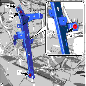
Text in Illustration *a Screw *b Bolt *c Nut Remove the screw.
-
Remove the bolt, 2 nuts and No. 1 instrument panel brace sub-assembly.
-
-
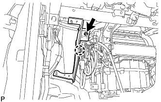
REMOVE NO. 2 INSTRUMENT PANEL BRACE SUB-ASSEMBLY
-
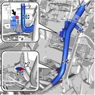
Text in Illustration *a Earth Wire Remove the bolt and disconnect the earth wire.
-
Disconnect the connector.
-
Disengage each clamp.
-
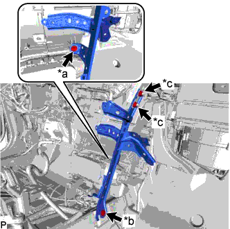
Text in Illustration *a Screw *b Bolt *c Nut Remove the screw.
-
Remove the bolt, 2 nuts and No. 2 instrument panel brace sub-assembly.
-
-
REMOVE NO. 1 HEATER TO REGISTER DUCT
-
Disengage the clamp.
-
Using a clip remover, remove the 3 clips and No. 1 heater to register duct.
-
-
REMOVE INSTRUMENT PANEL SAFETY PAD CAP
-
Text in Illustration *A for LH Side *B for RH Side *a Protective Tape Put protective tape around the 5 instrument panel safety pad caps.
-
Using a screwdriver, remove the 5 instrument panel safety pad caps.
-
-
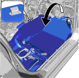
REMOVE INSTRUMENT PANEL REINFORCEMENT ASSEMBLY WITH AIR CONDITIONING UNIT
Note
-
Be sure to support the air conditioning unit assembly when removing it because failure to do so may cause the bracket of the air conditioning unit assembly to break.
-
When disassembling the air conditioning unit, eliminate static electricity by touching the vehicle body to prevent the components from being damaged.
-
Disengage each clamp.
-
w/ Telematics Transceiver:
-
Disengage each clamp.
-
-
Disengage the 3 claws to open the 3 clamps as shown in the illustration.
-
Disconnect the connector from the airbag sensor assembly as shown in the illustration.
Text in Illustration *1 Airbag Sensor Assembly - - Note
When disconnecting any airbag connector, take care not to damage the airbag wire harness.
-
Disconnect each connector.
-
Disengage each clamp.
-
w/ PTC Heater:
-
for U660E Automatic Transmission / Transaxle:
-
Remove the lower shift lever assembly Click here.
-
Remove the shift lever support Click here.
-
-
for U760E Automatic Transmission / Transaxle:
-
Remove the lower shift lever assembly Click here.
-
Remove the shift lever support Click here.
-
-
Remove the bolt.
-
Disconnect the connector.
-
-
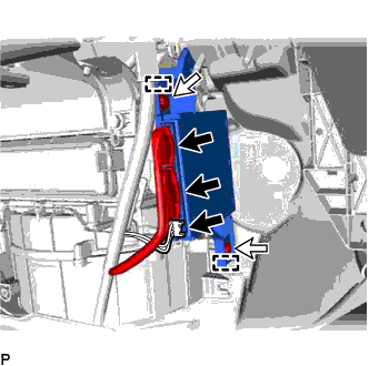
Using a screwdriver, disengage the 2 claws to unlock the retainer as shown in the illustration.
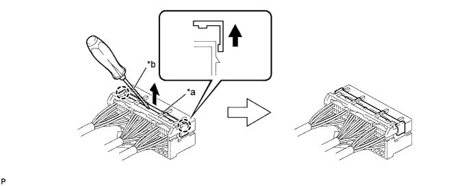
Text in Illustration *a Retainer *b Protective Tape -
Disengage the claw and disconnect the airbag connector as shown in the illustration.

-
for LHD:
-
Remove the 2 nuts and disconnect the connector holder.
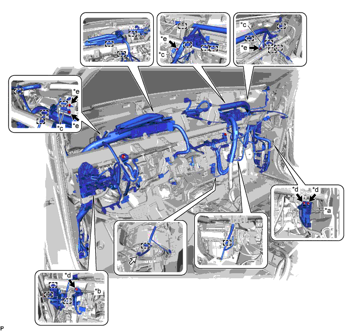
Text in Illustration *a Connector Holder *b Protector *c Earth Wire *d Nut *e Bolt - - -
Remove the nut and disconnect the protector.
-
Remove the 4 bolts and disconnect the 4 earth wires.
-
Disconnect the connector.
-
Disengage each clamp.
-
-
for RHD:
-
Remove the 2 nuts and disconnect the connector holder.
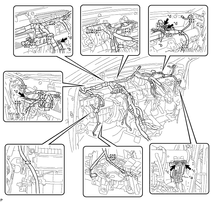
Text in Illustration *a Connector Holder *b Earth Wire *c Nut *d Bolt -
Remove the 4 bolts and disconnect the 4 earth wires.
-
Disconnect the connector.
-
Disengage each clamp.
-
-
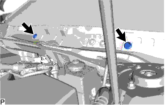
Remove the 2 hole plugs.
-
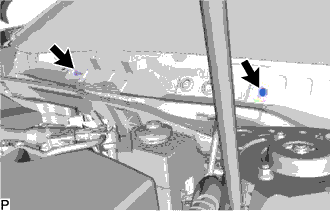
Remove the 2 bolts.
-
Disconnect the drain cooler hose.
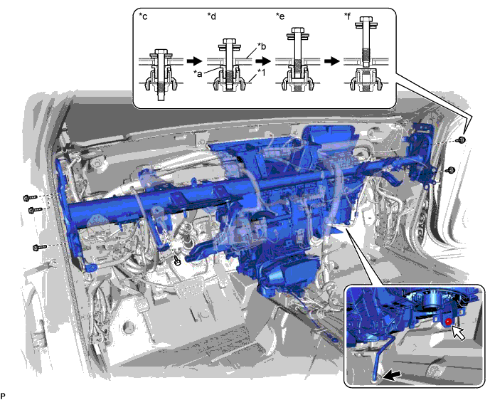
Text in Illustration *1 Instrument Panel Reinforcement Assembly - - *a Movable Collar *b Body *c Step 1 *d Step 2 *e Step 3 *f Step 4 -
Remove the 6 bolts and nut as shown in the illustration.
-
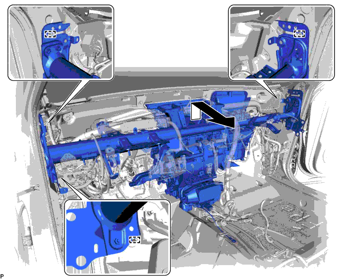
Disengage the 3 guides and remove the instrument panel reinforcement with air conditioning unit as shown in the illustration.
-
-
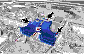
REMOVE AIR CONDITIONING UNIT ASSEMBLY
-
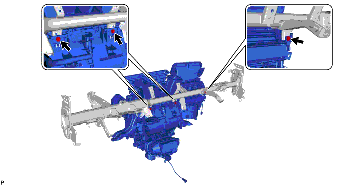
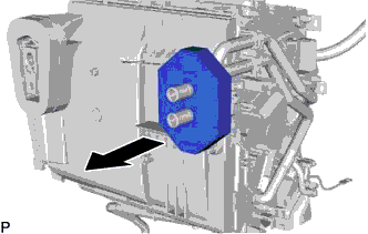
Remove the 3 bolts and air conditioning unit assembly from the instrument panel reinforcement assembly.
-
-
REMOVE BLOWER ASSEMBLY
for LHD: Click here
for RHD: Click here
-
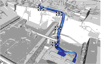
REMOVE AIR CONDITIONING HARNESS ASSEMBLY (for LHD)
-
Disconnect each connector.
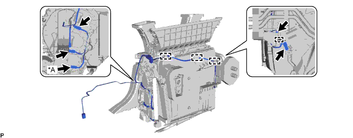
Text in Illustration *A for 3 Zone Type - - -
Disengage each clamp and remove the air conditioning harness assembly.
-
-
REMOVE AIR CONDITIONING HARNESS ASSEMBLY (for RHD)
-
Disconnect each connector.
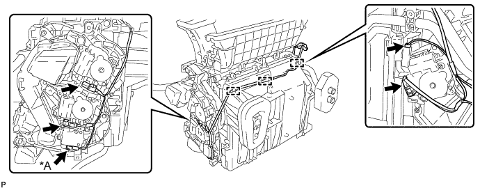
Text in Illustration *A for 3 Zone Type - - -
Disengage each clamp and remove the air conditioning harness assembly.
-
-
REMOVE NO. 6 HEATER TO REGISTER DUCT ASSEMBLY
-
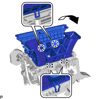
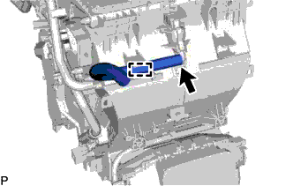
Disengage the 2 claws and 2 guides to remove the No. 6 heater to register duct assembly as shown in the illustration.
-
-
REMOVE NO. 1 AIR DUCT SUB-ASSEMBLY
-
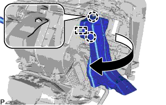
Disengage the 2 claws and guide to remove the No. 1 air duct sub-assembly as shown in the illustration.
-
-
REMOVE NO. 4 AIR DUCT SUB-ASSEMBLY (for RHD)
-
Disengage the 2 claws and guide to remove the No. 4 air duct sub-assembly as shown in the illustration.
-
-
REMOVE HEATER PACKING
-
Remove the heater packing as shown in the illustration.
-
-
REMOVE COOLER THERMISTOR HOSE
-
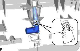
Disengage the clamp and remove the cooler thermistor hose.
-
-
REMOVE ASPIRATOR PIPE
-
Disengage the 2 claws and remove the aspirator pipe.
-
-
REMOVE DRAIN COOLER HOSE
-
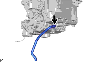
Remove the drain cooler hose.
-