ROOM TEMPERATURE SENSOR REMOVAL

-
PRECAUTION
Note
After turning the engine switch off, waiting time may be required before disconnecting the cable from the negative (-) battery terminal. Therefore, make sure to read the disconnecting the cable from the negative (-) battery terminal notices before proceeding with work Click here.
-
DISCONNECT CABLE FROM NEGATIVE BATTERY TERMINAL
Note
When disconnecting the cable, some systems need to be initialized after the cable is reconnected Click here.
-
REMOVE LOWER CENTER INSTRUMENT PANEL FINISH PANEL
-
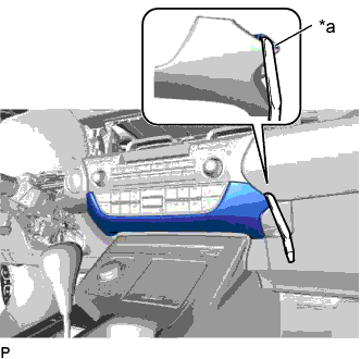
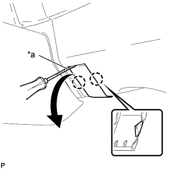
Text in Illustration *a Lower Center Instrument Panel Finish Panel Hole Insert a moulding remover as shown in the illustration.
-
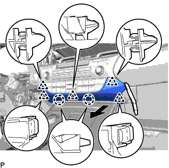
Using a moulding remover, disengage the 2 claws and 5 clips and remove the lower center instrument panel finish panel as shown in the illustration.
-
-
REMOVE FRONT DOOR SCUFF PLATE
-
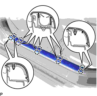
Disengage the 10 claws and remove the front door scuff plate LH.
-
-
REMOVE COWL SIDE TRIM BOARD
-
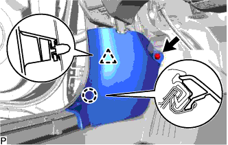
Remove the clip.
-
Disengage the claw and clip, and remove the cowl side trim board LH.
-
-
REMOVE FRONT DOOR OPENING TRIM COVER
-
Disengage the 3 claws.
-
Disengage the guide and remove the front door opening trim cover LH.
-
-
REMOVE INSTRUMENT SIDE PANEL
-
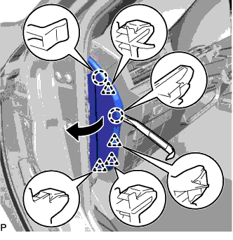
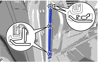
Using a moulding remover, disengage the 2 claws and 4 clips as shown in the illustration.
-
Disengage the 2 guides and remove the instrument side panel LH as shown in the illustration.
-
-
DISCONNECT HOOD LOCK CONTROL LEVER SUB-ASSEMBLY
-
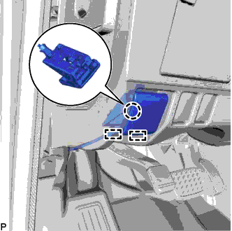
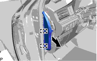
Disengage the claw and 2 guides to disconnect the hood lock control lever sub-assembly.
-
-
REMOVE LOWER NO. 1 INSTRUMENT PANEL FINISH PANEL
-
for LHD:
-
Remove the 2 bolts <B>.
-
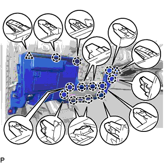
Disengage the 12 claws, 2 clips and guide.
-
Disconnect each connector and disengage each clamp to remove the lower No. 1 instrument panel finish panel.
-
-
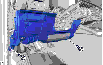
for RHD:
-
Text in Illustration *a Protective Tape Using a screwdriver, disengage the 2 claws and open the cover.
Tech Tips
Tape the screwdriver tip before use.
-
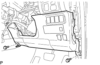
Remove the 2 bolts <B>.
-
Disengage the 6 claws, 3 clips and guide.
-
Disconnect each connector and disengage each clamp to remove the lower No. 1 instrument panel finish panel.
-
-
-
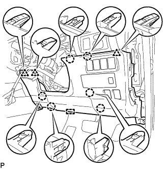
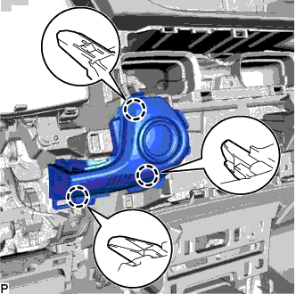
REMOVE INSTRUMENT CLUSTER FINISH PANEL SUB-ASSEMBLY
-
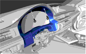
Remove the 2 screws <E>.
-
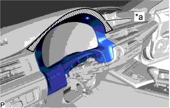
Text in Illustration *a Protective Tape Apply protective tape to the area shown in the illustration.
-
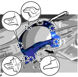
Using a moulding remover, disengage the 5 claws and 2 guides as shown in the illustration.
-
Disconnect the connector to remove the instrument cluster finish panel sub-assembly.
-
-
REMOVE SWITCH BASE
-
for LHD:
-
Disengage the 3 claws.
-
Disconnect the connector to remove the switch base.
-
-
for RHD:
-
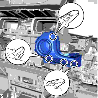
Disengage the 4 claws.
-
Disconnect the connector to remove the switch base.
-
-
-
REMOVE COOLER (ROOM TEMP. SENSOR) THERMISTOR
-
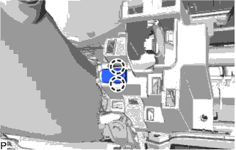
Disengage the 2 claws.
-
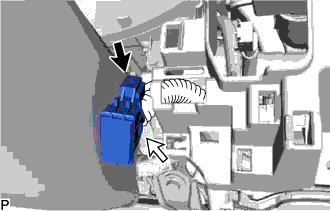
Disconnect the connector and cooler thermistor hose, and remove the cooler (room temp. sensor) thermistor.
-