AIR CONDITIONING SYSTEM, Diagnostic DTC:B14B2

| DTC Code | DTC Name |
|---|---|
| B14B2 | Lost Communication with Front Panel LIN |
DESCRIPTION
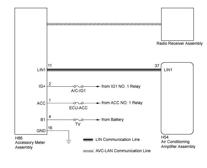
The accessory meter assembly communicates with the air conditioning amplifier assembly through the LIN communication system.
The accessory meter assembly receives an operation signal from the radio receiver assembly via AVC-LAN communication. It then converts this signal to a LIN communication signal and sends it to the air conditioning amplifier assembly.
| DTC No. | DTC Detection Condition | Trouble Area |
|---|---|---|
| B14B2 | Lost communication with the accessory meter assembly. |
|
WIRING DIAGRAM
INSPECTION PROCEDURE
Note
Inspect the fuses for circuits related to this system before performing the following inspection procedure.
PROCEDURE
-
CHECK HARNESS AND CONNECTOR (ACCESSORY METER ASSEMBLY - POWER SOURCE CIRCUIT)
-
Disconnect the H86 accessory meter assembly connector.
-
Measure the voltage according to the value(s) in the table below.
Standard Voltage Tester Connection Condition Specified Condition H86-4 (B1) - Body ground Always 11 to 14 V H86-2 (IG+) - Body ground Engine switch off Below 1 V H86-2 (IG+) - Body ground Engine switch on (IG) 11 to 14 V H86-1 (ACC) - Body ground Engine switch off Below 1 V H86-1 (ACC) - Body ground Engine switch on (ACC) 11 to 14 V
NG 
REPAIR OR REPLACE HARNESS OR CONNECTOR
OK 
-
-
CHECK HARNESS AND CONNECTOR (ACCESSORY METER ASSEMBLY - BODY GROUND)
-
Measure the resistance according to the value(s) in the table below.
Standard Resistance Tester Connection Condition Specified Condition H86-16 (GND) - Body ground Always Below 1 Ω
NG
REPAIR OR REPLACE HARNESS OR CONNECTOR
OK
-
-
CHECK HARNESS AND CONNECTOR (AIR CONDITIONING AMPLIFIER ASSEMBLY - ACCESSORY METER ASSEMBLY)
-
Disconnect the H54 air conditioning amplifier assembly connector.
-
Measure the resistance according to the value(s) in the table below.
Standard Resistance Tester Connection Condition Specified Condition H86-11 (LIN1) - H54-37 (LIN1) Always Below 1 Ω H86-11 (LIN1) - Body ground Always 10 kΩ or higher
NG
REPAIR OR REPLACE HARNESS OR CONNECTOR
OK
-
-
REPLACE ACCESSORY METER ASSEMBLY
-
Replace the accessory meter assembly Click here.
Tech Tips
Since the accessory meter assembly cannot be inspected while it is removed from the vehicle, replace the accessory meter assembly with a new or known good one and same problem occurs again.
OK Some problem does not occurs. Result Result Proceed to OK A NG (When troubleshooting according to Problem Symptoms Table) B NG (When troubleshooting according to the DTC) C
B
PROCEED TO NEXT SUSPECTED AREA SHOWN IN PROBLEM SYMPTOMS TABLE Click here
C
REPLACE AIR CONDITIONING AMPLIFIER ASSEMBLY Click here
A 
END (ACCESSORY METER ASSEMBLY WAS DEFECTIVE)
-