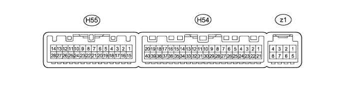
AIR CONDITIONING SYSTEM TERMINALS OF ECU

-
AIR CONDITIONING AMPLIFIER ASSEMBLY
Tech Tips
Check from the rear of the connector while it is connected to the air conditioning amplifier assembly.
Terminal No.
(Symbol)
Wiring Color Terminal Description Condition Specified Condition H54-1 (IG+) - H54-14 (GND) V - W-B Power source (IG) Engine switch on (IG) 11 to 14 V H54-1 (IG+) - H54-14 (GND) V - W-B Power source (IG) Engine switch off Below 1 V H54-2 (SOL+) - H54-14 (GND) W - W-B Compressor solenoid operation signal
-
Engine running
-
A/C switch: on
-
Blower switch: LO
Pulse generation
(See waveform 1)
H54-3 (PTC2) - H54-14 (GND)*1 L - W-B PTC heater assembly (quick heater assembly) operation signal
-
Engine running
-
ECO mode switch (integration control and panel assembly) on
-
Blower motor off
-
Temperature settings: except MAX HOT
-
Engine coolant temperature 70°C or lower
-
Ambient temperature 10°C or lower
11 to 14 V H54-3 (PTC2) - H54-14 (GND)*1 L - W-B PTC heater assembly (quick heater assembly) operation signal
-
Engine running
-
ECO mode switch (integration control and panel assembly) off
-
Blower motor on
-
Temperature settings: MAX HOT
-
Engine coolant temperature 70°C or lower
-
Ambient temperature 10°C or lower
Below 1 V H54-4 (ECOS) - H54-14 (GND) SB - W-B ECO mode switch (integration control and panel assembly) signal
-
Engine switch on (IG)
-
ECO mode switch (integration control and panel assembly) not turned
11 to 14 V H54-4 (ECOS) - H54-14 (GND) SB - W-B ECO mode switch (integration control and panel assembly) signal
-
Engine switch on (IG)
-
ECO mode switch (integration control and panel assembly) being turned and held at ECO position
Below 1 V H54-5 (TAM) - H54-13 (SG-2) P - L Ambient temperature sensor signal
-
Engine switch on (IG)
-
Ambient temperature: 25°C (77°F)
1.35 to 1.75 V H54-5 (TAM) - H54-13 (SG-2) P - L Ambient temperature sensor signal
-
Engine switch on (IG)
-
Ambient temperature: 40°C (104°F)
0.9 to 1.2 V H54-7 (FLOQ) - H54-13 (SG-2) G - L A/C flow sensor signal
-
Engine switch on (IG)
-
A/C switch: off
3.8 to 4.2 V H54-7 (FLOQ) - H54-13 (SG-2) G - L A/C flow sensor signal
-
Engine switch on (IG)
-
A/C switch: on
-
Blower switch: HI
0.7 to 3.8 V H54-8 (LOCK) - H54-14 (GND)*3 P - W-B A/C lock sensor signal
-
Engine running
-
Blower switch: LO
-
A/C switch: on
Pulse generation
(See waveform 2)
H54-9 (PRE) - H54-13 (SG-2) V - L Air conditioning pressure sensor signal
-
Engine running
-
A/C system operating
-
Refrigerant pressure: Abnormal pressure (more than 3025 kPa (30.9 kgf/cm2, 439 psi))
4.80 V or higher H54-9 (PRE) - H54-13 (SG-2) V - L Air conditioning pressure sensor signal
-
Engine running
-
A/C system operating
-
Refrigerant pressure: Abnormal pressure (less than 176 kPa (1.8 kgf/cm2, 25 psi))
Below 0.50 V H54-9 (PRE) - H54-13 (SG-2) V - L Air conditioning pressure sensor signal
-
Engine running
-
A/C system operating
-
Refrigerant pressure: Normal pressure (less than 3025 kPa (30.9 kgf/cm2, 439 psi) and more than 176 kPa (1.8 kgf/cm2, 25 psi))
0.50 to 4.80 V H54-10 (S5-3) - H54-13 (SG-2) BR - L Power supply for air conditioning pressure sensor Engine switch on (IG) 4.75 to 5.25 V H54-10 (S5-3) - H54-13 (SG-2) BR - L Power supply for air conditioning pressure sensor Engine switch off Below 1 V H54-11 (CANH) - H54-12 (CANL) G - W CAN communication system CAN communication occurring Pulse generation H54-13 (SG-2) - Body ground L - Body ground Ground for air conditioning pressure sensor, ambient temperature sensor, A/C lock sensor, A/C flow sensor, smog ventilation sensor Always Below 1 V H54-14 (GND) - Body ground W-B - Body ground Ground for main power supply Always Below 1 V H54-15 (NANO) - H54-14 (GND)*2 R - W-B No. 1 ion generator sub-assembly operation signal
-
Engine switch on (IG)
-
Blower switch: LO
Below 1 V H54-15 (NANO) - H54-14 (GND)*2 R - W-B No. 1 ion generator sub-assembly operation signal
-
Engine switch on (IG)
-
Blower switch: off
4.75 to 5.25 V H54-20 (MGC) - H54-14 (GND)*3 B - W-B Magnetic clutch operation signal
-
Engine running
-
Blower switch: LO
-
A/C switch: off
11 to 14 V H54-20 (MGC) - H54-14 (GND)*3 B - W-B Magnetic clutch operation signal
-
Engine running
-
Blower switch: LO
-
A/C switch: on
Below 1 V H54-21 (B) - H54-14 (GND) GR - W-B Power source (Back-up) Always 11 to 14 V H54-22 (BLW) - H54-14 (GND) R - W-B Blower motor speed control signal
-
Engine switch on (IG)
-
Blower switch: LO
Pulse generation
(See waveform 3)
H54-26 (NAIN) - H54-14 (GND)*2 L - W-B No. 1 ion generator sub-assembly operation condition signal
-
Engine switch on (IG)
-
Blower switch: LO
Below 1 V H54-26 (NAIN) - H54-14 (GND)*2 L - W-B No. 1 ion generator sub-assembly operation condition signal
-
Engine switch on (IG)
-
Blower switch: off
11 to 14 V H54-29 (TR) - H54-34 (SG-1) P - LG Room temperature sensor signal
-
Engine switch on (IG)
-
Cabin temperature: 25°C (77°F)
1.8 to 2.2 V H54-29 (TR) - H54-34 (SG-1) P - LG Room temperature sensor signal
-
Engine switch on (IG)
-
Cabin temperature: 40°C (104°F)
1.2 to 1.6 V H54-30 (S5-1) - H54-13 (SG-2) L - L Power supply for A/C flow sensor Engine switch off Below 1 V H54-30 (S5-1) - H54-13 (SG-2) L - L Power supply for A/C flow sensor Engine switch on (IG) 4.5 to 5.5 V H54-32 (TSP) - H54-14 (GND) Y - W-B Solar sensor signal (for front passenger side)
-
Engine switch on (IG)
-
Solar sensor subjected to electric light
0.8 to 4.3 V H54-32 (TSP) - H54-14 (GND) Y - W-B Solar sensor signal (for front passenger side)
-
Engine switch on (IG)
-
Solar sensor covered with a cloth
Below 0.8 V H54-33 (TSD) - H54-14 (GND) BE - W-B Solar sensor signal (for driver side)
-
Engine switch on (IG)
-
Solar sensor subjected to electric light
0.8 to 4.3 V H54-33 (TSD) - H54-14 (GND) BE - W-B Solar sensor signal (for driver side)
-
Engine switch on (IG)
-
Solar sensor covered with a cloth
Below 0.8 V H54-34 (SG-1) - Body ground LG - Body ground Ground for room temperature sensor Always Below 1 V H54-37 (LIN1) - H54-14 (GND)*4 B - W-B LIN communication signal Engine switch on (IG) Pulse generation H54-40 (PTC1) - H54-14 (GND)*1 G - W-B PTC heater assembly (quick heater assembly) operation signal
-
Engine running
-
ECO mode switch (integration control and panel assembly) on
-
Blower motor off
-
Temperature settings: except MAX HOT
-
Engine coolant temperature 70°C or lower
-
Ambient temperature 10°C or lower
11 to 14 V H54-40 (PTC1) - H54-14 (GND)*1 G - W-B PTC heater assembly (quick heater assembly) operation signal
-
Engine running
-
ECO mode switch (integration control and panel assembly) off
-
Blower motor on
-
Temperature settings: MAX HOT
-
Engine coolant temperature 70°C or lower
-
Ambient temperature 10°C or lower
Below 1 V H55-3 (DGS) - H54-13 (SG-2) LG - L Smog ventilation sensor signal (HC, CO) After 30 seconds from engine switch on (IG) and sensor exposed to exhaust gas (HC, CO) 1.0 to 4.5 V H55-4 (DGS1) - H54-13 (SG-2) SB - L Smog ventilation sensor signal (NOx) After 30 seconds from engine switch on (IG) and sensor exposed to exhaust gas (NOx) 1.0 to 4.5 V z1-2 (BUS G) - Body ground - Ground for BUS IC Always Below 1 V z1-3 (BUS) - z1-2 (BUS G) - BUS IC control signal Engine switch on (IG) Pulse generation z1-4 (B BUS) - z1-2 (BUS G) - Power supply for BUS IC Always 11 to 14 V z1-5 (SGA) - Body ground - Ground for evaporator temperature sensor Always Below 1 V z1-6 (TEA) - z1-5 (SGA) - Evaporator temperature sensor signal
-
Engine switch on (IG)
-
Evaporator temperature: 0°C (32°F)
1.7 to 2.1 V z1-6 (TEA) - z1-5 (SGA) - Evaporator temperature sensor signal
-
Engine switch on (IG)
-
Evaporator temperature: 15°C (59°F)
0.9 to 1.3 V
-
*1: w/ Quick Heater Assembly
-
*2: w/ Ion Generator Assembly
-
*3: for 2GR-FE
-
*4: w/o Multi-display
-
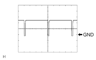
Waveform 1:
Item Content Terminal No. H54-2 (SOL+) - H54-14 (GND) Tool Setting 5 V/DIV., 500 μs/DIV. Vehicle Condition
-
Engine running
-
A/C switch: on
-
Blower switch: LO
-
-
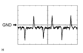
Waveform 2:
Item Content Terminal No. H54-8 (LOCK) - H54-13 (SG-2) Tool Setting 200 mV/DIV., 10 ms./DIV. Vehicle Condition
-
Engine running
-
Blower switch: LO
-
A/C switch: on
-
-
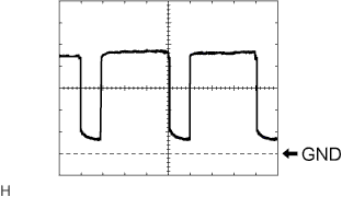
Waveform 3:
Item Content Terminal No. H54-22 (BLW) - H54-14 (GND) Tool Setting 1 V/DIV., 500 μs/DIV. Vehicle Condition
-
Engine switch on (IG)
-
Blower switch: LO
-
-
-
MULTI-MEDIA MODULE RECEIVER ASSEMBLY (w/ Multi-display) Click here
-
RADIO RECEIVER ASSEMBLY (w/o Multi-display)
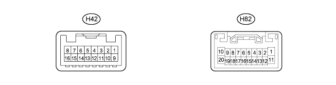
Tech Tips
Check from the rear of the connector while it is connected to the radio receiver assembly.
Terminal No.
(Symbol)
Wiring Color Terminal Description Condition Specified Condition H82-1 (B) - Body ground R - Body ground Power source (Back-up) Always 11 to 14 V H42-5 (TX+) R AVC-LAN communication signal - - H42-9 (GND) - Body ground W-B - Body ground Ground for radio receiver (A/C control panel) Always Below 1 V H42-13 (TX-) G AVC-LAN communication signal - - H42-16 (ACC) - H42-9 (GND) Y - W-B Power source (ACC) Engine switch off Below 1 V H42-16 (ACC) - H42-9 (GND) Y - W-B Power source (ACC) Engine switch on (ACC) 11 to 14 V -
MULTI-DISPLAY ASSEMBLY (w/ Multi-display) Click here
-
ACCESSORY METER ASSEMBLY (w/o Multi-display) Click here
-
COOLER CONTROL SWITCH ASSEMBLY (for 3 ZONE TYPE)

Tech Tips
Check from the rear of the connector while it is connected to the cooler control switch assembly.
Terminal No.
(Symbol)
Wiring Color Terminal Description Condition Specified Condition h2-1 (+B) - h2-16 (GND) R - W-B Power source (Back-up) Always 11 to 14 V h2-6 (ACC) - h2-16 (GND) P - W-B Power source (ACC) Engine switch off Below 1 V h2-6 (ACC) - h2-16 (GND) P - W-B Power source (ACC) Engine switch on (ACC) 11 to 14 V h2-7 (IG+) - h2-16 (GND) SB - W-B Power source (IG) Engine switch off Below 1 V h2-7 (IG+) - h2-16 (GND) SB - W-B Power source (IG) Engine switch on (IG) 11 to 14 V h2-8 (ILL+) - h2-16 (GND) LG - W-B Light control switch signal Light control switch off Below 1 V h2-8 (ILL+) - h2-16 (GND) LG - W-B Light control switch signal Light control switch tail or head position 11 to 14 V h2-10 (RLIN) - Body ground GR - Body ground LIN communication signal Engine switch on (IG) Pulse generation h2-16 (GND) - Body ground W-B - Body ground Ground for cooler control switch assembly Always Below 1 V