POWER WINDOW REGULATOR MOTOR (for Front Door) INSTALLATION

Tech Tips
-
Use the same procedure for both the RH and LH sides.
-
The procedure described below is for the LH side.
-
PRECAUTION
Note
After turning the engine switch off, waiting time may be required before disconnecting the cable from the negative (-) battery terminal. Therefore, make sure to read the disconnecting the cable from the negative (-) battery terminal notices before proceeding with work Click here.
-
INSTALL FRONT POWER WINDOW REGULATOR MOTOR ASSEMBLY
Note
The regulator arm must be below the intermediate position when installing the power window regulator motor.
-
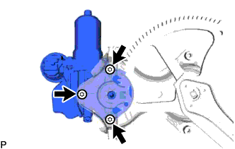
Using a T25 "TORX" socket wrench, install the front power window regulator motor assembly with the 3 screws.
- Torque:
- 5.4 N*m { 55 kgf*cm, 48 in.*lbf }
Tech Tips
A new front window regulator uses self-tapping screws to thread new installation holes when the self-tapping screws are inserted.
-
-
INSTALL FRONT DOOR WINDOW REGULATOR ASSEMBLY
-
Apply MP grease to the sliding parts of the front door window regulator assembly.
-
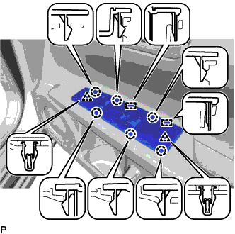
Install the temporary bolt to the front door window regulator assembly.
-
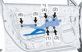
Text in Illustration *1 Temporary Bolt Temporarily install the front door window regulator assembly.
-
Tighten the temporary bolt and 5 bolts to install the front door window regulator assembly.
Tech Tips
Tighten the bolts in the order shown in the illustration.
- Torque:
- 11 N*m { 112 kgf*cm, 8 ft.*lbf }
-
-
INSTALL FRONT DOOR GLASS SUB-ASSEMBLY
-
Connect the cable to the negative (-) battery terminal.
-
Connect the multiplex network master switch assembly and move the front door glass sub-assembly so that the door glass bolts can be seen.
-
Disconnect the cable from the negative (-) battery terminal.
-
Disconnect the multiplex network master switch assembly.
-
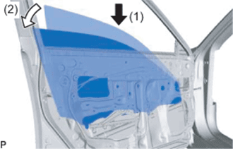
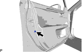
Insert the front door glass sub-assembly into the front door panel along the front door glass run as indicated by the arrows and in the order shown in the illustration.
-
Install the front door glass sub-assembly with the 2 bolts.
- Torque:
- 5.5 N*m { 56 kgf*cm, 49 in.*lbf }
-
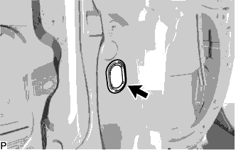
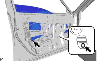
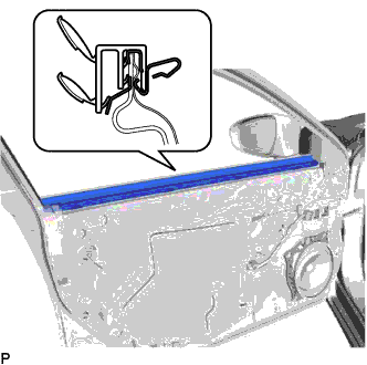
Install the grommet.
-
-
INSTALL FRONT DOOR SERVICE HOLE COVER
-
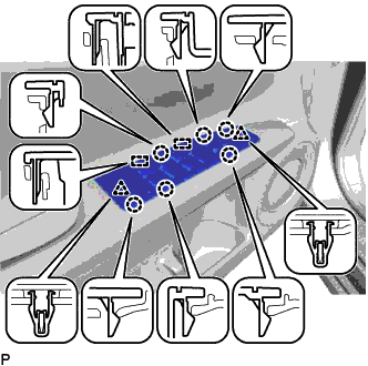
Apply new butyl tape to the front door panel.
-
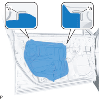
Text in Illustration *a Reference Point Pass the front door lock remote control cable assembly and front door inside locking cable assembly through a new front door service hole cover.
-
Attach the front door service hole cover according to the reference points on the front door panel.
Note
Securely install the front door service hole cover preventing wrinkles and air bubbles.
-
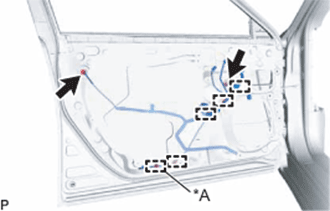
Text in Illustration *A for LH Side Engage each clamp.
-
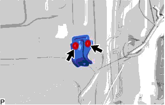
Connect the 2 connectors.
-
-
INSTALL FRONT DOOR ARMREST SET BRACKET
-
Install the front door armrest set bracket with the 2 screws.
-
-
INSTALL FRONT NO. 1 SPEAKER ASSEMBLY
-
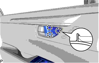
Install the front No. 1 speaker assembly with the 4 screws.
Note
Do not touch the speaker cone.
-
Connect the connector.
-
-
INSTALL FRONT DOOR INNER GLASS WEATHERSTRIP
-
Install the front door inner glass weatherstrip.
-
-
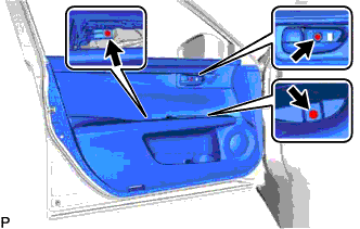
INSTALL FRONT DOOR TRIM BOARD SUB-ASSEMBLY
-
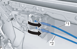
Text in Illustration *1 Front Door Inside Locking Cable Assembly *2 Front Door Lock Remote Control Cable Assembly Connect the front door lock remote control cable assembly and front door inside locking cable assembly.
-
w/ Memory:
-
Connect the connector.
-
-
w/ Illumination:
-
Connect the connector.
-
-
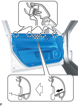
Text in Illustration *1 Reference Boss Engage the front door trim board sub-assembly with the 4 claws and reference boss as shown in the illustration.
-
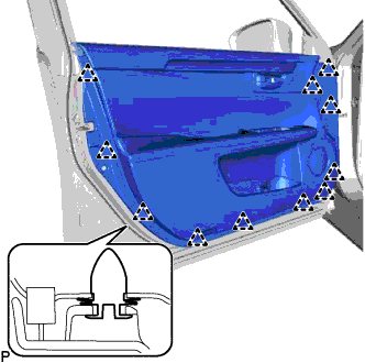
Engage the 11 clips to temporary install the front door trim board sub-assembly.
-
Install the 3 screws to install the front door trim board sub-assembly.
-
-
INSTALL FRONT DOOR NO. 1 STIFFENER CUSHION
-
Install the front door No. 1 stiffener cushion with the screw.
-
-
INSTALL COURTESY LIGHT ASSEMBLY
-
Connect the connector.
-
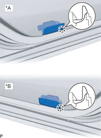
Text in Illustration *A for LH Side *B for RH Side Engage the claw to install the courtesy light assembly.
-
-
INSTALL DOOR PULL HANDLE COVER
-
Install the door pull handle cover.
-
-
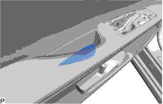
INSTALL MULTIPLEX NETWORK MASTER SWITCH ASSEMBLY WITH FRONT DOOR ARMREST BASE PANEL (for Driver Side)
-
Connect each connector.
-
Engage the 2 guides, 2 clips and 6 claws, to install the multiplex network master switch assembly with front door armrest base panel.
-
-
INSTALL POWER WINDOW REGULATOR SWITCH ASSEMBLY WITH FRONT DOOR ARMREST BASE PANEL (for Front Passenger Side)
-
Connect each connector.
-
Engage the 2 guides, 2 clips and 6 claws, to install the power window regulator switch assembly with front door armrest base panel.
-
-
INSTALL FRONT DOOR INSIDE HANDLE BEZEL PLUG
-
Engage the 3 claws to install the front door inside handle bezel plug.
-
-
CONNECT CABLE TO NEGATIVE BATTERY TERMINAL
Note
When disconnecting the cable, some systems need to be initialized after the cable is reconnected Click here.
-
INITIALIZE POWER WINDOW CONTROL SYSTEM
-
INSPECT POWER WINDOW OPERATION