POWER WINDOW REGULATOR MOTOR (for Front Door) REMOVAL

Tech Tips
-
Use the same procedure for both the RH and LH sides.
-
The procedure described below is for the LH side.
-
PRECAUTION
Note
After turning the engine switch off, waiting time may be required before disconnecting the cable from the negative (-) battery terminal. Therefore, make sure to read the disconnecting the cable from the negative (-) battery terminal notices before proceeding with work Click here.
-
DISCONNECT CABLE FROM NEGATIVE BATTERY TERMINAL
Note
When disconnecting the cable, some systems need to be initialized after the cable is reconnected Click here.
-
REMOVE FRONT DOOR INSIDE HANDLE BEZEL PLUG
-

Using a moulding remover, disengage the 3 claws and remove the front door inside handle bezel plug as shown in the illustration.
-
-
REMOVE MULTIPLEX NETWORK MASTER SWITCH ASSEMBLY WITH FRONT DOOR ARMREST BASE PANEL (for Driver Side)
-
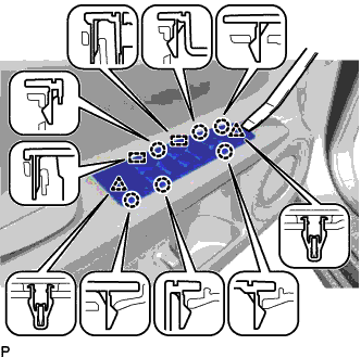
Using a moulding remover, disengage the 2 clips, 6 claws and 2 guides as shown in the illustration.
-
Disconnect each connector and remove the multiplex network master switch assembly with front door armrest base panel.
-
-
REMOVE POWER WINDOW REGULATOR SWITCH ASSEMBLY WITH FRONT DOOR ARMREST BASE PANEL (for Front Passenger Side)
-
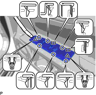
Using a moulding remover, disengage the 2 clips, 6 claws and 2 guides as shown in the illustration.
-
Disconnect each connector and remove the power window regulator switch assembly with front door armrest base panel.
-
-
REMOVE DOOR PULL HANDLE COVER
-
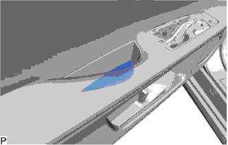
Remove the door pull handle cover.
-
-
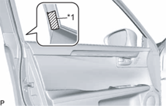
REMOVE COURTESY LIGHT ASSEMBLY
-
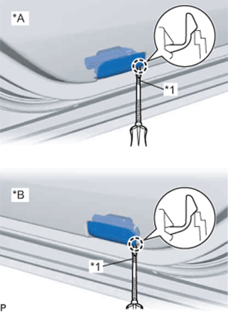
Text in Illustration *A for LH Side *B for RH Side *1 Protective Tape Using a screwdriver with its tip wrapped with protective tape, disengage the claw.
-
Disconnect the connector and remove the courtesy light assembly.
-
-
REMOVE FRONT DOOR NO. 1 STIFFENER CUSHION
-
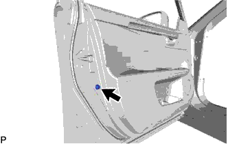
Remove the screw and front door No. 1 stiffener cushion.
-
-
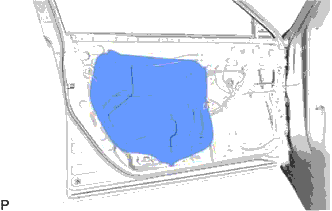
REMOVE FRONT DOOR TRIM BOARD SUB-ASSEMBLY
-
Text in Illustration *1 Protective Tape Put protective tape around the front door panel.
-
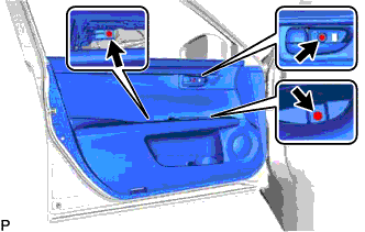
Remove the 3 screws.
-
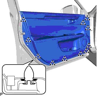
Using a clip remover, disengage the 11 clips.
-
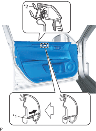
Text in Illustration *1 Reference Boss *2 Front Door Inner Glass Weatherstrip Pull out the front door trim board sub-assembly in the direction indicated by the arrow as shown in the illustration.
-
Disengage the reference boss from the front door panel.
-
Raise the front door trim board sub-assembly and disconnect the front door trim board sub-assembly together with the front door inner glass weatherstrip.
-
w/ Memory:
-
Disconnect the connector.
-
-
w/ Illumination:
-
Disconnect the connector.
-
-
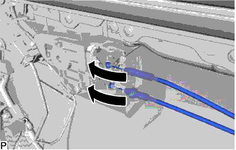
Disconnect the front door lock remote control cable assembly and front door inside locking cable assembly to remove the front door trim board sub-assembly together with the front door inner glass weatherstrip.
-
-
REMOVE FRONT DOOR INNER GLASS WEATHERSTRIP
-
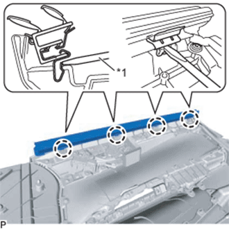
Text in Illustration *1 Screwdriver Using a screwdriver, disengage the 4 claws and remove the front door inner glass weatherstrip from the front door trim board sub-assembly as shown in the illustration.
-
-
REMOVE FRONT NO. 1 SPEAKER ASSEMBLY
-
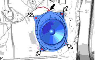
Disconnect the connector.
-
Remove the 4 screws and front No. 1 speaker assembly.
Note
Do not touch the speaker cone.
-
-
REMOVE FRONT DOOR ARMREST SET BRACKET
-
Remove the 2 screws and front door armrest set bracket.
-
-
REMOVE FRONT DOOR SERVICE HOLE COVER
-
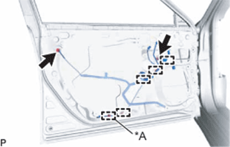
Text in Illustration *A for LH Side Disconnect the 2 connectors.
-
Disengage each clamp.
-
Remove the front door service hole cover.
Tech Tips
Remove any remaining butyl tape from the door.
-
-
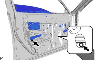
REMOVE FRONT DOOR GLASS SUB-ASSEMBLY
-
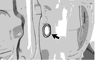
Remove the grommet.
-
Connect the cable to the negative (-) battery terminal.
-
Connect the multiplex network master switch assembly and move the front door glass sub-assembly so that the door glass bolts can be seen.
-
Disconnect the cable from the negative (-) battery terminal.
-
Disconnect the multiplex network master switch assembly.
-
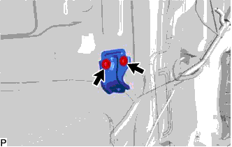
Remove the 2 bolts.
Note
After the bolts are removed, do not allow the front door glass sub-assembly to fall.
-
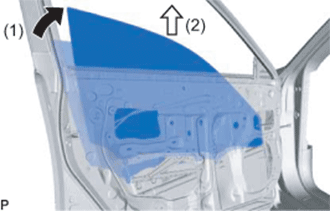
Remove the front door glass sub-assembly as indicated by the arrows, in the order shown in the illustration.
Note
Do not damage the front door glass sub-assembly.
-
-
REMOVE FRONT DOOR WINDOW REGULATOR ASSEMBLY
-
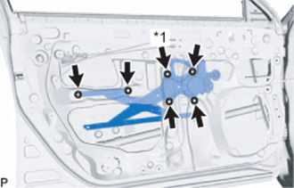
Text in Illustration *1 Temporary Bolt Loosen the temporary bolt.
Note
Do not remove the temporary bolt. If the temporary bolt is removed, the front door window regulator assembly may fall and cause damage.
-
Remove the 5 bolts.
-
Remove the front door window regulator assembly.
-
Remove the temporary bolt from the front door window regulator assembly.
-
-
REMOVE FRONT POWER WINDOW REGULATOR MOTOR ASSEMBLY
-
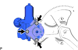
Using a T25 "TORX" socket wrench, remove the 3 screws and front power window regulator motor assembly.
-