FUEL INJECTOR INSTALLATION

-
INSTALL FUEL INJECTOR ASSEMBLY
Tech Tips
Perform "Inspection After Repair" after replacing the fuel injector assembly Click here.
-
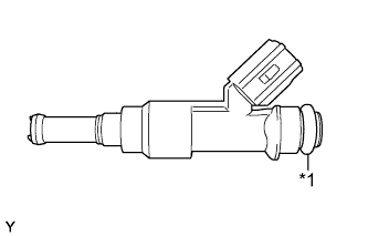
Text in Illustration *1 O-ring Apply a light coat of spindle oil or gasoline to new O-rings, and install them to each fuel injector assembly.
-
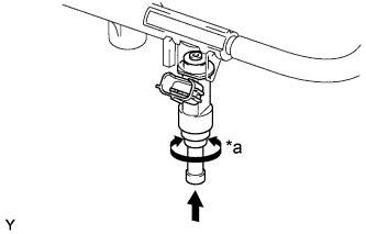
Text in Illustration *a Turn 
Push Apply a light coat of spindle oil or gasoline where the fuel delivery pipe contacts each O-ring.
-
Push and twist each fuel injector assembly to install it into the fuel delivery pipe sub-assembly.
-
Position each fuel injector connector outward.
Note
-
Be careful not to twist the O-rings.
-
After installing a fuel injector assembly, check that it turns smoothly. If not, reinstall it with a new O-ring.
-
-
-
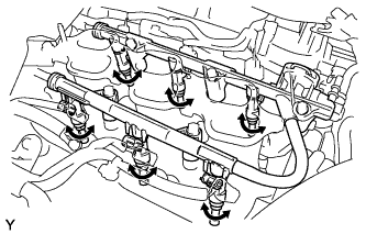
INSTALL FUEL DELIVERY PIPE SUB-ASSEMBLY
-
Install 6 new injector vibration insulators to the intake manifold.
-
Place the fuel delivery pipe sub-assembly with the 6 fuel injector assemblies in position on the intake manifold.
Note
Be careful not to drop the fuel injector assemblies when installing the fuel delivery pipe sub-assembly.
-
Temporarily install the 5 bolts which are used to hold the fuel delivery pipe sub-assembly to the intake manifold.
Note
After installing the fuel injector assemblies, check that they turn smoothly. If not, reinstall them with new O-rings.
-
Tighten the 5 bolts which are used to hold the fuel delivery pipe sub-assembly to the intake manifold.
- Torque:
- 21 N*m { 214 kgf*cm, 15 ft.*lbf }
-
Connect the 6 fuel injector connectors.
-
-
CONNECT FUEL TUBE SUB-ASSEMBLY
-
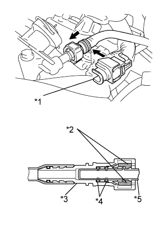
Text in Illustration *1 No. 2 Fuel Pipe Clamp *2 Retainer *3 Fuel Tube Connector *4 O-ring *5 Fuel Pipe Push Push in the fuel tube connector onto the fuel pipe until the fuel tube connector makes a "click" sound.
Note
-
Before connecting the fuel tube connector and fuel pipe, check that there is no damage or foreign matter on the connecting part of the fuel pipe.
-
After connecting the fuel tube connector and fuel pipe, check that they are securely connected by trying to pull them apart.
-
-
Install the No. 2 fuel pipe clamp.
-
-
INSTALL INTAKE AIR SURGE TANK ASSEMBLY
-
CONNECT CABLE TO NEGATIVE BATTERY TERMINAL
Note
When disconnecting the cable, some systems need to be initialized after the cable is reconnected Click here.
-
INSPECT FOR FUEL LEAK
-
Check fuel pump operation.
-
Connect the GTS to the DLC3.
-
Turn the engine switch on (IG) and turn the GTS on.
Note
Do not start the engine.
-
Enter the following menus: Powertrain / Engine / Active Test / Control the Fuel Pump / Speed.
-
Check for pressure in the fuel tube sub-assembly from the fuel pipe. Check that sounds of fuel flowing from the fuel tank can be heard. If no sounds can be heard, check the integration relay, fuel pump, ECM and wiring connectors.
-
-
Inspect for fuel leaks.
-
Check that there are no fuel leaks from the fuel system after doing any maintenance or repairs. If there is a fuel leak, repair or replace parts as necessary.
-
-
Turn the engine switch off.
-
Disconnect the GTS from the DLC3.
-