FUEL INJECTOR REMOVAL

Tech Tips
Perform "Inspection After Repair" after replacing a fuel injector assembly Click here.
-
PRECAUTION
Note
After turning the engine switch off, waiting time may be required before disconnecting the cable from the negative (-) battery terminal. Therefore, make sure to read the disconnecting the cable from the negative (-) battery terminal notices before proceeding with work Click here.
-
DISCHARGE FUEL SYSTEM PRESSURE
-
DISCONNECT CABLE FROM NEGATIVE BATTERY TERMINAL
Note
When disconnecting the cable, some systems need to be initialized after the cable is reconnected Click here.
-
REMOVE NO. 1 ENGINE COVER SUB-ASSEMBLY
-
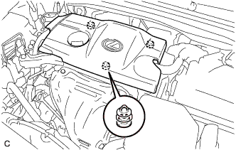
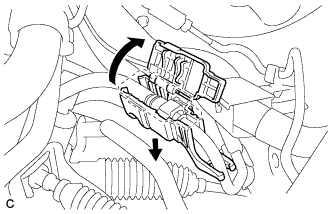
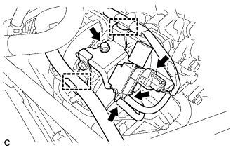
Lift the rear of the No. 1 engine cover sub-assembly to detach it from the 2 pins.
-
Lift the front of the No. 1 engine cover sub-assembly to detach the it from the pin and remove it.
Note
Attempting to disengage both front and rear pins at the same time may cause the No. 1 engine cover sub-assembly to break.
-
-
REMOVE AIR CLEANER CAP SUB-ASSEMBLY
-
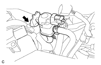
Disconnect the vacuum switching valve assembly from the air cleaner cap sub-assembly.
-
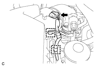
Disconnect the mass air flow meter connector and separate the 2 wire harness clamps from the air cleaner cap sub-assembly.
-
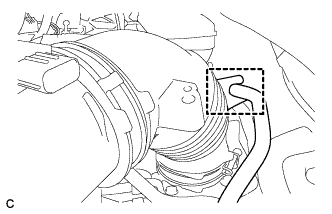
Separate the fuel vapor feed hose from the air cleaner cap sub-assembly.
-
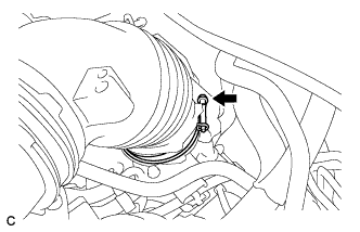
Disconnect the ventilation hose from the cylinder head cover.
-
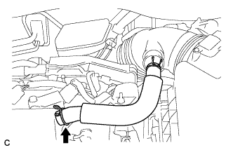
Loosen the hose clamp and disconnect the air cleaner cap sub-assembly from the throttle with motor body assembly.
-
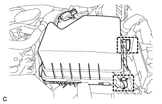
Release the 2 clamps and remove the air cleaner cap sub-assembly.
-
-
DISCONNECT FUEL TUBE SUB-ASSEMBLY
Note
Remove any dirt or foreign matter on the fuel tube connector and fuel pipe before performing this work.
-
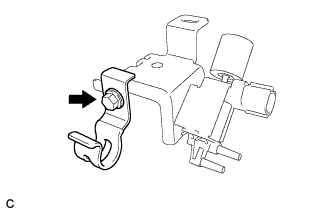
Disengage the claw and remove the No. 1 fuel pipe clamp.
-
Disconnect the fuel tube sub-assembly from the fuel pipe.
-
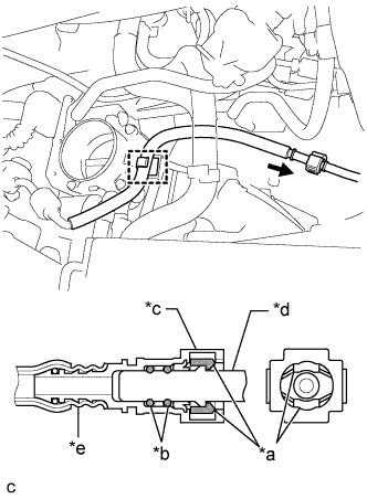
Text in Illustration *a Retainer *b O-ring *c Fuel Tube Connector *d Fuel Pipe *e Nylon Tube 
Pinch 
Pull Pinch the retainer of the fuel tube connector, and then pull the fuel tube connector off of the fuel pipe.
Note
Be sure to disconnect the fuel tube connector by hand.
-
If the fuel tube connector and fuel pipe are stuck, push and pull the fuel tube connector to release it. Pull the fuel tube connector off of the fuel pipe carefully.
Note
-
Be sure to disconnect the fuel tube connector by hand.
-
Do not allow any scratches or foreign matter to get on the parts when disconnecting them as the fuel tube connector has O-rings that seal the fuel pipe.
-
Do not forcibly bend, twist or turn the nylon tube.
-
-
Check if there is any foreign matter on the sealing surfaces of the disconnected fuel lines. Clean them if necessary.
-
Cover the disconnected fuel pipe and fuel tube connector with plastic bags to prevent damage and contamination.
-
-
Disengage the clamp to disconnect the fuel tube sub-assembly from the fuel hose clamp.
-
-
REMOVE VACUUM SWITCHING VALVE ASSEMBLY (for ACIS)
-
Disconnect the union to vacuum tube hose and wire harness clamp.
-
Disconnect the 2 vacuum hoses and connector.
-
Remove the bolt and vacuum switching valve assembly from the intake manifold.
-
Remove the bolt and vacuum hose clamp.
-
-
DISCONNECT WIRE HARNESS
-
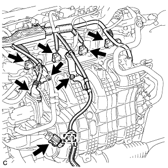
Disconnect the 4 fuel injector assembly connectors, throttle body with motor assembly connector and sensor wire connector.
-
Remove the 2 bolts and separate the 2 wire harness brackets from the intake manifold.
-
Disengage the clamp to disconnect the wire harness.
-
-
REMOVE FUEL DELIVERY PIPE
-
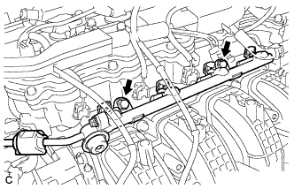
Remove the 2 bolts and fuel delivery pipe with the 4 fuel injector assemblies.
Note
Do not drop the fuel injector assemblies when removing the fuel delivery pipe.
-
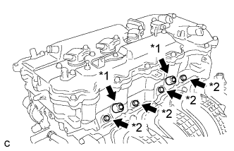
Text in Illustration *1 Fuel Delivery Spacer *2 Injector Vibration Insulator Remove the 2 fuel delivery spacers from the cylinder head.
-
Remove the 4 injector vibration insulators from the cylinder head.
-
-
REMOVE FUEL INJECTOR ASSEMBLY
-
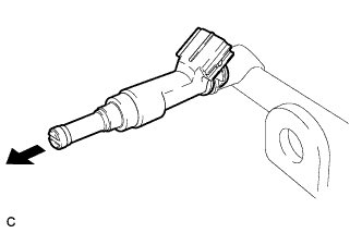
Pull the 4 fuel injector assemblies out of the fuel delivery pipe.
-
Remove the O-ring from each fuel injector assembly.
-
For reinstallation, attach a tag or label with the corresponding cylinder number to each fuel injector assembly.
Note
Protect the fuel injector assemblies by covering them with plastic bags.
-