FUEL INJECTOR REMOVAL

Tech Tips
Perform "Inspection After Repair" after replacing the fuel injector assembly Click here.
-
PRECAUTION
Note
After turning the engine switch off, waiting time may be required before disconnecting the cable from the negative (-) battery terminal. Therefore, make sure to read the disconnecting the cable from the negative (-) battery terminal notice before proceeding with work Click here.
-
DISCHARGE FUEL SYSTEM PRESSURE
-
DISCONNECT CABLE FROM NEGATIVE BATTERY TERMINAL
Note
When disconnecting the cable, some systems need to be initialized after the cable is reconnected Click here.
-
REMOVE NO. 1 ENGINE COVER SUB-ASSEMBLY
-
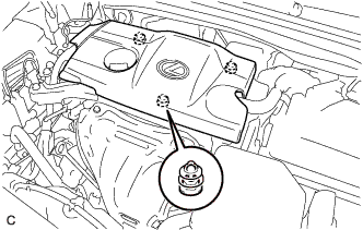
Lift the rear of the No. 1 engine cover sub-assembly to detach it from the 2 pins.
-
Lift the front of the No. 1 engine cover sub-assembly to detach the it from the pin and remove it.
Note
Attempting to disengage both front and rear pins at the same time may cause the No. 1 engine cover sub-assembly to break.
-
-
REMOVE AIR CLEANER CAP SUB-ASSEMBLY
-
Disconnect the vacuum switching valve assembly from the air cleaner cap sub-assembly.
-
Disconnect the mass air flow meter connector and separate the 2 wire harness clamps from the air cleaner cap sub-assembly.
-
Separate the fuel vapor feed hose from the air cleaner cap sub-assembly.
-
Disconnect the ventilation hose from the cylinder head cover.
-
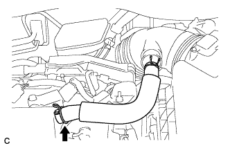
Loosen the hose clamp and disconnect the air cleaner cap sub-assembly from the throttle with motor body assembly.
-
Release the 2 clamps and remove the air cleaner cap sub-assembly.
-
-
DISCONNECT FUEL TUBE SUB-ASSEMBLY
-
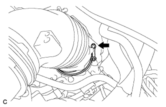
Remove the No. 1 fuel pipe clamp.
-
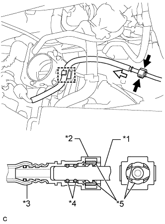
Text in Illustration *1 Fuel Pipe *2 Fuel Tube Connector *3 Nylon Tube *4 O-ring *5 Retainer 
Pinch 
Pull Pinch the retainer of the fuel tube connector, and then pull the fuel tube connector off of the fuel pipe.
Note
-
Check for foreign matter on the fuel tube around the fuel tube connector. Clean it if necessary. Foreign matter can affect the ability of the O-ring to seal the fuel tube connector and fuel pipe.
-
Do not use any tools to separate the fuel tube connector and fuel pipe.
-
Do not forcibly bend, kink or twist the nylon tube.
-
Keep the fuel tube connector and fuel pipe free from foreign matter.
-
If the fuel tube connector and fuel pipe are stuck, push and pull to release them.
-
Cover the fuel tube connector and fuel pipe with plastic bags to prevent damage and contamination.
-
-
Disconnect the fuel tube sub-assembly from the fuel hose clamp.
-
-
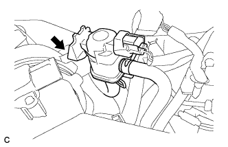
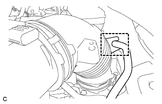
REMOVE VACUUM SWITCHING VALVE ASSEMBLY (for ACIS)
-
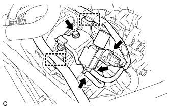
Disconnect the union to vacuum tube hose and wire harness clamp.
-
Disconnect the 2 vacuum hoses and connector.
-
Remove the bolt and vacuum switching valve assembly from the intake manifold.
-
Remove the bolt and vacuum hose clamp.
-
-
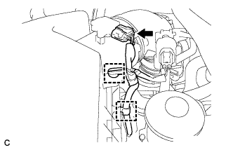
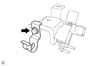
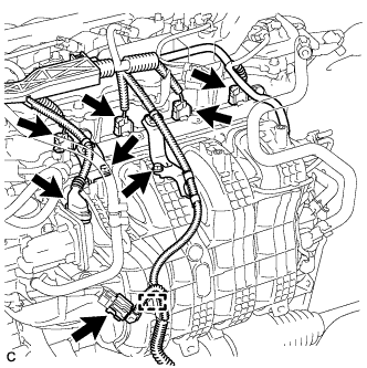
DISCONNECT WIRE HARNESS
-
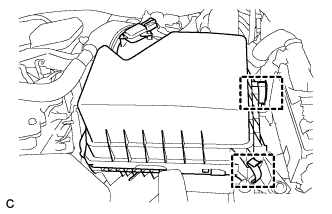
Disconnect the 4 fuel injector connectors.
-
Disconnect the 2 connectors.
-
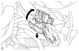
Remove the 2 bolts and separate the 2 wire harness brackets.
-
Disengage the clamp to disconnect the wire harness.
-
-
REMOVE FUEL DELIVERY PIPE
-
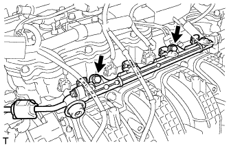
Remove the 2 bolts, and then remove the fuel delivery pipe together with the 4 fuel injector assemblies.
Note
Be careful not to drop the fuel injector assemblies when removing the fuel delivery pipe.
-
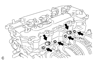
Remove the 2 fuel delivery spacers from the cylinder head.
-
Remove the 4 injector vibration insulators from the cylinder head.
-
-
REMOVE FUEL INJECTOR ASSEMBLY
-
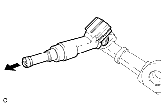
Pull the 4 fuel injector assemblies out of the fuel delivery pipe.
-
Remove the O-ring from each fuel injector assembly.
-
For reinstallation, attach a tag or label to each fuel injector shaft.
Note
Protect the fuel injector assemblies by covering them with plastic bags.
-