ENGINE UNIT INSTALLATION

Tech Tips
Perform "Inspection After Repair" after replacing the engine assembly Click here.
-
INSTALL ENGINE OIL LEVEL SENSOR
-
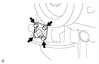
Install the engine oil level sensor with the 4 bolts and a new gasket.
- Torque:
- 8.2 N*m { 84 kgf*cm, 73 in.*lbf }
-
-
INSTALL ENGINE COOLANT TEMPERATURE SENSOR
-
Install a new gasket onto the engine coolant temperature sensor.
-
Using a 19 mm ball joint lock nut wrench, install the engine coolant temperature sensor.
- Torque:
- 20 N*m { 204 kgf*cm, 15 ft.*lbf }
Note
Use the torque value compensation formula to calculate the torque value for use when a torque wrench is combined with a tool such as a ball joint lock nut wrench Click here.
Tech Tips
Perform "Inspection After Repair" after replacing the engine coolant temperature sensor Click here.
-
Connect the engine coolant temperature sensor connector.
-
Connect the 2 engine wire clamps.
-
-
INSTALL KNOCK SENSOR WIRE
-
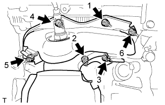
Connect the 3 clamps, 2 knock sensor connectors and knock sensor wire connector.
-
-
INSTALL KNOCK CONTROL SENSOR
-
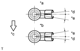
Text in Illustration *a for Bank 1 *b for Bank 2 *c Front of Vehicle *d 5° *e 10° Install the 2 knock control sensors with the 2 bolts so that the knock control sensor installation position is as shown in the illustration.
- Torque:
- 20 N*m { 204 kgf*cm, 15 ft.*lbf }
Note
Make sure that each knock control sensor is in the correct position.
-
Connect the 2 knock control sensor connectors.
-
-
INSTALL ENGINE OIL PRESSURE SWITCH ASSEMBLY
-
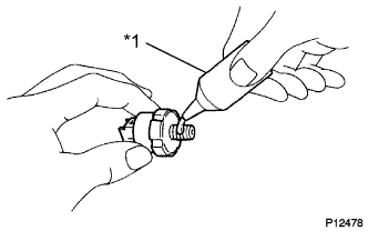
Text in Illustration *1 Adhesive Clean the threads of the engine oil pressure switch assembly. Apply adhesive to 2 or 3 threads of the engine oil pressure switch assembly.
Adhesive Toyota Genuine Adhesive 1344, Three Bond 1344 or equivalent -
Using a 24 mm deep socket wrench, install the engine oil pressure switch assembly.
- Torque:
- 15 N*m { 153 kgf*cm, 11 ft.*lbf }
Note
Do not start the engine within 1 hour after installation to prevent oil leaks.
-
-
INSTALL NO. 1 VACUUM SWITCHING VALVE
-
Install the No. 1 vacuum switching valve with the bolt.
- Torque:
- 10 N*m { 102 kgf*cm, 7 ft.*lbf }
-
-
INSTALL WATER PUMP PULLEY
-
Temporarily install the water pump pulley with the 4 bolts.
-
Using SST, hold the water pump pulley.
- SST
- 09960-10010 ( 09962-01000, 09963-00700 )
-
Tighten the 4 bolts.
- Torque:
- 21 N*m { 214 kgf*cm, 15 ft.*lbf }
-
-
INSTALL NO. 2 IDLER PULLEY SUB-ASSEMBLY
-
Install the idler pulley cover plate, No. 2 idler pulley sub-assembly and No. 2 idler pulley cover plate with the bolt.
- Torque:
- 54 N*m { 551 kgf*cm, 40 ft.*lbf }
-
-
INSTALL NO. 2 TIMING GEAR COVER
-
Install the No. 2 timing gear cover with the 2 bolts.
- Torque:
- 6.0 N*m { 61 kgf*cm, 53 in.*lbf }
-
-
INSTALL V-RIBBED BELT TENSIONER ASSEMBLY
-
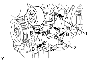
Temporarily install the V-ribbed belt tensioner assembly with the 5 bolts.
Tech Tips
Each bolt length is as follows:
A: 70 mm (2.76 in.)
B: 33 mm (1.30 in.)
-
Install the V-ribbed belt tensioner assembly by tightening the bolt 1 and bolt 2 in the order shown in the illustration.
- Torque:
- 43 N*m { 438 kgf*cm, 32 ft.*lbf }
-
Tighten the other bolts.
- Torque:
- 43 N*m { 438 kgf*cm, 32 ft.*lbf }
-
-
INSTALL EXHAUST MANIFOLD SUB-ASSEMBLY LH
-
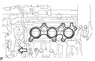
Install a new gasket as shown in the illustration.
Text in Illustration 
Engine Front -
Install the exhaust manifold sub-assembly LH with the 6 nuts in the order shown in the illustration.
- Torque:
- 21 N*m { 214 kgf*cm, 15 ft.*lbf }
-
-
INSTALL NO. 2 EXHAUST MANIFOLD HEAT INSULATOR
-
Install the No. 2 exhaust manifold heat insulator with the 3 bolts.
- Torque:
- 8.5 N*m { 87 kgf*cm, 75 in.*lbf }
-
-
INSTALL NO. 2 MANIFOLD STAY
-
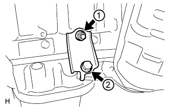
Tighten the bolt and nut in the order shown in the illustration.
- Torque:
- 34 N*m { 347 kgf*cm, 25 ft.*lbf }
-
-
INSTALL NO. 2 ENGINE OIL LEVEL DIPSTICK GUIDE
-
Install a new O-ring to the No. 2 engine oil level dipstick guide.
-
Apply a light coat of engine oil to the O-ring.
-
Push in the No. 2 engine oil level dipstick guide end into the engine oil level dipstick guide.
-
Install the No. 2 engine oil level dipstick guide with the bolt.
- Torque:
- 21 N*m { 214 kgf*cm, 15 ft.*lbf }
-
Install the engine oil level dipstick.
-
-
INSTALL EXHAUST MANIFOLD SUB-ASSEMBLY RH
-
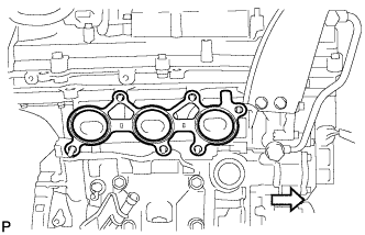
Install a new gasket as shown in the illustration.
Text in Illustration Engine Front -
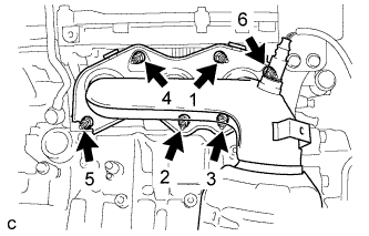
Install the exhaust manifold sub-assembly RH with the 6 nuts in the order shown in the illustration.
- Torque:
- 21 N*m { 214 kgf*cm, 15 ft.*lbf }
-
-
INSTALL INTAKE MANIFOLD
-
Set 2 new gaskets on each cylinder head sub-assembly.
Note
-
Align the port holes of the gasket and cylinder head sub-assembly.
-
Make sure that the gasket is installed in the correct direction.
-
-
Set the intake manifold on the cylinder head sub-assembly.
-
Install and tighten the 6 bolts and 4 nuts uniformly in several steps.
- Torque:
- 21 N*m { 214 kgf*cm, 15 ft.*lbf }
-
-
INSTALL NO. 2 ENGINE MOUNTING STAY RH
-
Install the No. 2 engine mounting stay RH with the bolt.
- Torque:
- 21 N*m { 214 kgf*cm, 15 ft.*lbf }
-
-
INSTALL IGNITION COIL ASSEMBLY
-
Install the 6 ignition coil assemblies with the 6 bolts.
- Torque:
- 10 N*m { 102 kgf*cm, 7 ft.*lbf }
Tech Tips
Perform "Inspection After Repair" after replacing an ignition coil assembly Click here.
-
Connect the 6 ignition coil assembly connectors.
-
Connect the 2 wire harness clamps.
-
Install the nut.
- Torque:
- 8.0 N*m { 82 kgf*cm, 71 in.*lbf }
-
-
INSTALL NO. 1 SURGE TANK STAY
Note
Do not apply oil to the bolt as listed below:
Oil Application Prohibited Bolt Bolt for No. 1 surge tank stay and cylinder head cover
-
Install the No. 1 surge tank stay with the bolt.
- Torque:
- 21 N*m { 214 kgf*cm, 15 ft.*lbf }
-
-
INSTALL THROTTLE BODY BRACKET
Note
Do not apply oil to the bolt as listed below:
Oil Application Prohibited Bolt Bolt for throttle body bracket and cylinder head cover
-
Install the throttle body bracket with the bolt.
- Torque:
- 21 N*m { 214 kgf*cm, 15 ft.*lbf }
-
-
INSTALL INTAKE AIR SURGE TANK ASSEMBLY
Note
Do not apply oil to the bolts listed below
Oil Application Prohibited Bolt Bolt for Intake Air Surge Tank Assembly and Intake Manifold Bolt for No. 1 Surge Tank Stay and Intake Air Surge Tank Assembly Bolt for Throttle Body Bracket and Intake Air Surge Tank Assembly
-
Install 3 new gaskets to the intake air surge tank assembly.
-
Temporarily install the intake air surge tank assembly with the 4 bolts and 2 nuts.
-
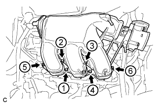
Using a 5 mm hexagon socket wrench, in several steps, uniformly tighten the 4 bolts and 2 nuts in the order shown in the illustration.
- Torque:
- Bolt
- 18 N*m { 184 kgf*cm, 13 ft.*lbf }
- Nut
- 16 N*m { 163 kgf*cm, 12 ft.*lbf }
-
Install the throttle body bracket and No. 1 surge tank stay with the 2 bolts.
- Torque:
- 21 N*m { 214 kgf*cm, 15 ft.*lbf }
-
Install the vacuum hose clamp with the bolt.
- Torque:
- 5.4 N*m { 55 kgf*cm, 48 in.*lbf }
Tech Tips
Install the vacuum hose clamp so that its tab is in contact with the No. 1 surge tank stay.
-
Connect the connector to the intake air control valve assembly.
-
Connect the 2 water by-pass hoses and fuel vapor feed hose.
-
Connect the connector and wire harness clamp to the throttle body assembly.
-
Connect the hose clamp and union to check valve hose.
-
Connect the ventilation hose to the intake air surge tank assembly.
-
-
INSTALL ENGINE HANGERS
-
Install the 2 engine hangers with the 4 bolts.
Part No. Item Part No. No. 1 Engine Hanger 12281-31120 No. 2 Engine Hanger 12282-31100 Bolt 91671-10825 - Torque:
- 33 N*m { 337 kgf*cm, 24 ft.*lbf }
-
Attach an engine sling device and hang the engine with a chain block.
-