ENGINE ASSEMBLY REMOVAL

-
PRECAUTION
CAUTION:
The engine assembly with transmission is very heavy. Be sure to follow the procedure described in the repair manual, or the engine lifter may suddenly drop.
Note
After turning the engine switch off, waiting time may be required before disconnecting the cable from the negative (-) battery terminal. Therefore, make sure to read the disconnecting the cable from the negative (-) battery terminal notices before proceeding with work Click here.
-
RECOVER REFRIGERANT FROM AIR CONDITIONING SYSTEM
-
Start the engine.
-
Operate the cooler compressor under the conditions shown below:
Item Condition Indicator Operating Time 3 minutes or more - Temperature setting Max cool - Blower speed High 
Engine Idling - A/C switch On 
This causes most of the compressor oil from the various components of the A/C system to collect in the A/C compressor.
Tech Tips
It is not necessary to operate the cooler compressor if the A/C does not operate because of compressor lock, etc.
-
Stop the engine.
-
Recover the refrigerant from the A/C system using a refrigerant recovery unit.
Tech Tips
Use the refrigerant recovery unit in accordance with the manufacturer's instruction manual.
-
-
DISCHARGE FUEL SYSTEM PRESSURE
-
ALIGN FRONT WHEELS FACING STRAIGHT AHEAD
-
DISCONNECT CABLE FROM NEGATIVE BATTERY TERMINAL
Note
When disconnecting the cable, some systems need to be initialized after the cable is reconnected Click here.
-
REMOVE FRONT WHEELS
-
REMOVE FRONT WHEEL OPENING EXTENSION PAD RH
-
REMOVE ENGINE UNDER COVER RH
-
REMOVE FRONT FENDER APRON SEAL RH
-
REMOVE FRONT WHEEL OPENING EXTENSION PAD LH
-
REMOVE ENGINE UNDER COVER LH
-
REMOVE FRONT FENDER APRON SEAL LH
-
DRAIN ENGINE OIL
-
Remove the oil filler cap.
-
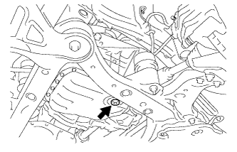
Remove the oil pan drain plug and gasket, and drain the oil into a container.
-
Clean the oil pan drain plug.
-
Install the oil pan drain plug with a new gasket.
- Torque:
- 40 N*m { 408 kgf*cm, 30 ft.*lbf }
-
-
DRAIN ENGINE COOLANT
Note
Do not remove the radiator cap sub-assembly, cylinder block drain cock plugs and radiator drain cock plug while the engine and radiator assembly are still hot. Pressurized, hot engine coolant and steam may be released and cause serious burns.
-
Loosen the radiator drain cock plug.
-
Loosen the 2 cylinder block drain cock plugs.
-
Remove the radiator cap sub-assembly.
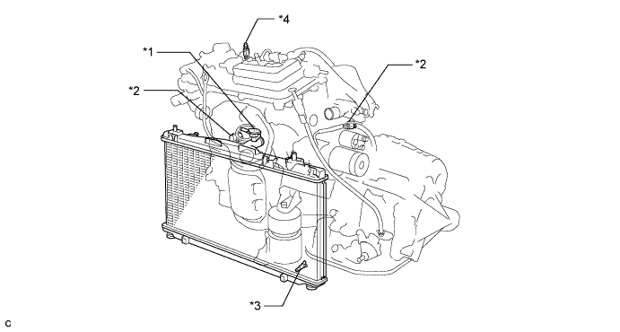
Text in Illustration *1 Radiator Cap Sub-assembly *2 Cylinder Block Drain Cock Plug *3 Radiator Drain Cock Plug *4 Air Drain Cock Plug Tech Tips
Collect the engine coolant in a container and dispose of it according to the regulations in your area.
-
-
DRAIN AUTOMATIC TRANSAXLE FLUID
-
Remove the front wheel opening extension pad LH, engine under cover LH and front fender apron seal LH.
-
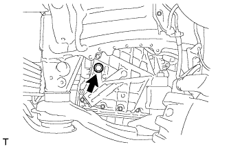
Remove the refill plug and gasket from the automatic transaxle assembly.
-
Using a 6 mm hexagon socket wrench, remove the overflow plug and gasket from the automatic transaxle assembly.
-

Text in Illustration *1 No. 1 Transmission Oil Filler Tube *2 Hexagon Socket Wrench *a Overflow Plug Hole Using a 6 mm hexagon socket wrench, remove the No. 1 transmission oil filler tube from the automatic transaxle oil pan sub-assembly.
-
Drain automatic transaxle fluid from the automatic transaxle assembly.
-
Text in Illustration *1 No. 1 Transmission Oil Filler Tube *2 Hexagon Socket Wrench *a Overflow Plug Hole Using a 6 mm hexagon socket wrench, install the No. 1 transmission oil filler tube to the automatic transaxle oil pan sub-assembly.
- Torque:
- 1.7 N*m { 17 kgf*cm, 15 in.*lbf }
-
Using a 6 mm hexagon socket wrench, install a new gasket and the overflow plug to the automatic transaxle assembly.
- Torque:
- 40 N*m { 408 kgf*cm, 30 ft.*lbf }
-
Temporarily install the gasket and refill plug to the automatic transaxle assembly.
Tech Tips
Reuse the old gasket as the plug will be removed again to adjust the fluid level.
-
-
REMOVE COOL AIR INTAKE DUCT SEAL
-
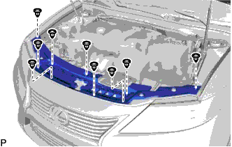
Remove the 9 clips and cool air intake duct seal.
-
-
REMOVE V-BANK COVER SUB-ASSEMBLY
-
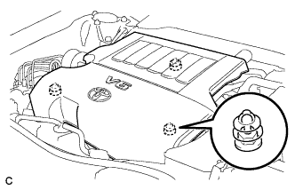
Hold the front of the V-bank cover sub-assembly and raise it to disengage the 2 retainers on the front of the V-bank cover sub-assembly. Continue to raise the V-bank cover sub-assembly to disengage the retainer on the rear of the V-bank cover sub-assembly and remove the V-bank cover sub-assembly.
Note
Attempting to disengage both front and rear retainers at the same time may cause the V-bank cover sub-assembly to break.
-
-
REMOVE INLET NO. 2 AIR CLEANER
-
Disconnect the 2 wire harness clamps and vacuum hose clamp.
-
Remove the 2 bolts and inlet No. 2 air cleaner.
-
-
REMOVE AIR CLEANER CAP SUB-ASSEMBLY
-
Disconnect the mass air flow meter connector and wire harness clamp.
-
Disconnect the 3 hoses.
-
Disconnect the ventilation hose from the air cleaner cap sub-assembly.
-
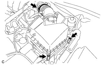
Loosen the hose clamp and separate the air cleaner cap sub-assembly from the throttle with motor body assembly.
-
Release the 2 clamps and remove the air cleaner cap sub-assembly.
-
-
REMOVE AIR CLEANER FILTER ELEMENT SUB-ASSEMBLY
-
Remove the air cleaner filter element sub-assembly from the air cleaner case sub-assembly.
-
-
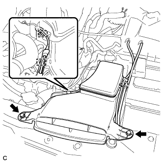
REMOVE AIR CLEANER CASE SUB-ASSEMBLY
-
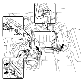
Disconnect the 3 wire harness clamps, connector, vacuum hose and No. 1 fuel vapor feed hose.
-
Remove the 2 bolts and air cleaner case sub-assembly.
-
-
REMOVE BATTERY
-
Disconnect the positive (+) cable from the positive (+) battery terminal.
-
Loosen the nut and remove the bolt.
-
Remove the battery clamp, battery and battery tray.
-
-
REMOVE INLET NO. 1 AIR CLEANER
-
Disengage the pin and remove the inlet No. 1 air cleaner.
-
-
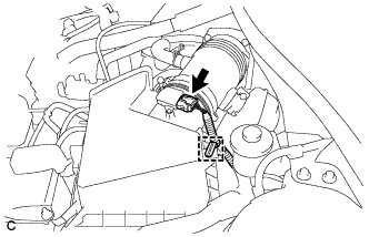
REMOVE INTAKE AIR RESONATOR SUB-ASSEMBLY
-
Disengage the clamp and disconnect the 2 vacuum hoses.
-
Remove the 2 bolts and intake air resonator sub-assembly.
-
-
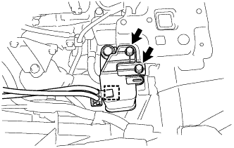
REMOVE NO. 2 ENGINE MOUNTING STAY RH
-

Remove the bolt, 2 nuts and No. 2 engine mounting stay RH.
-
-
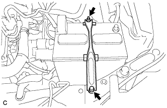
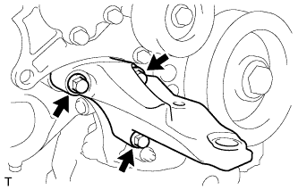
REMOVE ENGINE MOVING CONTROL ROD SUB-ASSEMBLY
-
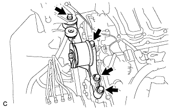
Remove the 4 bolts and engine moving control rod sub-assembly.
-
-
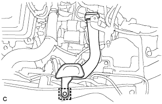
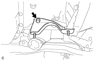
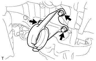
REMOVE NO. 3 ENGINE MOUNTING STAY RH
Tech Tips
Perform this procedure only when replacement of the engine moving control rod or No. 3 engine mounting stay RH is necessary.
-
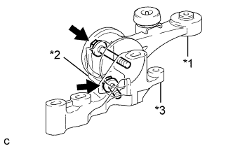
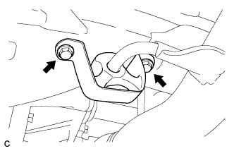
Text in Illustration *1 Engine Moving Control Rod *2 No. 3 Engine Mounting Stay RH *3 Engine Moving Control Rod Bracket Remove the 2 bolts, engine moving control rod and No. 3 engine mounting stay RH from the engine moving control rod bracket.
-
-
SEPARATE EARTH WIRE
-
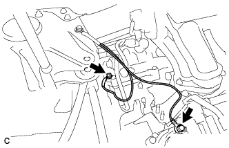
Remove the 2 bolts and separate the earth wire from the engine assembly.
-
-
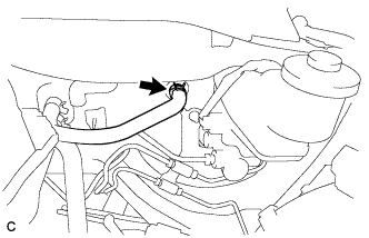
DISCONNECT NO. 1 FUEL VAPOR FEED HOSE
-
Disconnect the No. 1 fuel vapor feed hose.
-
-
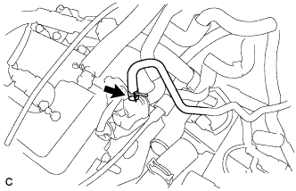
DISCONNECT UNION TO CHECK VALVE HOSE
-
Disconnect the union to check valve hose from the brake booster.
-
-
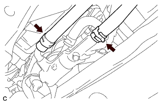
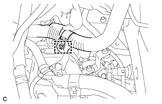
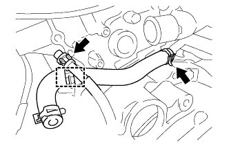
DISCONNECT NO. 1 RADIATOR HOSE
-
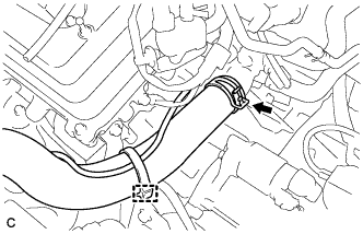
Remove the hose clamp to separate the air fuel ratio sensor wire from the No. 1 radiator hose.
-
Disconnect the No. 1 radiator hose.
-
-
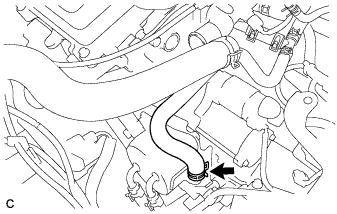
DISCONNECT NO. 2 RADIATOR HOSE
-
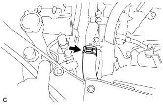
Disconnect the No. 2 radiator hose.
-
-
REMOVE OIL COOLER TUBE SUB-ASSEMBLY (w/ ATF Warmer)
-
w/ Transmission Oil Thermostat:
-
Disconnect the 2 oil cooler tube sub-assemblies.
-
-
-
DISCONNECT OUTLET NO. 1 OIL COOLER HOSE (w/o ATF Warmer)
-
Disconnect the outlet No. 1 oil cooler hose from the automatic transaxle assembly.
-
-
DISCONNECT INLET NO. 1 OIL COOLER HOSE (w/o ATF Warmer)
-
Disconnect the inlet No. 1 oil cooler hose from the automatic transaxle assembly.
-
-
DISCONNECT NO. 3 WATER BY-PASS HOSE (w/ ATF Warmer)
-
Disconnect the No. 3 water by-pass hose from the transmission oil cooler.
-
-
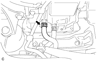
DISCONNECT INLET HEATER WATER HOSE (w/ ATF Warmer)
-
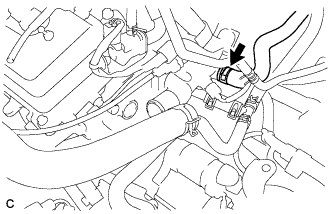
Disconnect the inlet heater water hose.
-
-
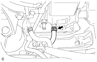
DISCONNECT WATER HOSE SUB-ASSEMBLY (w/ ATF Warmer)
-
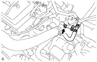
Disconnect the water hose sub-assembly.
-
-
DISCONNECT INLET HEATER WATER HOSE (w/o ATF Warmer)
-
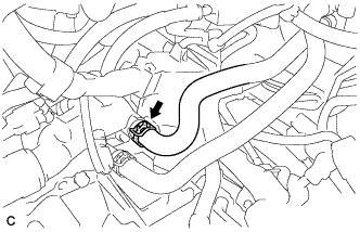
Disconnect the inlet heater water hose.
-
-
DISCONNECT OUTLET HEATER WATER HOSE (w/o ATF Warmer)
-
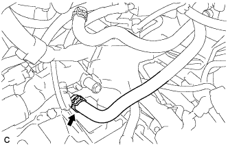
Disconnect the outlet heater water hose.
-
-
REMOVE STARTER ASSEMBLY
-
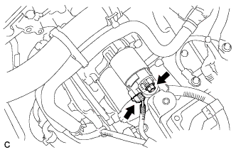
Disconnect the connector.
-
Open the cap, remove the nut and disconnect the wire harness.
-
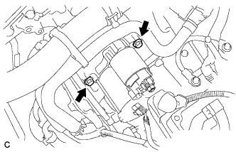
Remove the 2 bolts and starter assembly.
-
-
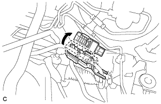
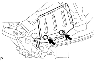
DISCONNECT ENGINE WIRE
-
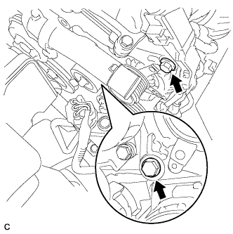
Remove the No. 1 relay block cover.
-

Remove the 2 nuts and disconnect the wire clamp.
-
Using a screwdriver, unlock the clamp and separate the engine wire from the engine room relay block.
-
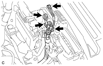
Disconnect the 4 connectors.
-
Using a screwdriver, unlock the clamp and separate the engine wire from the engine room relay block.
-
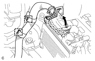
Pull up the lever to disconnect the ECM connector.
-
Disconnect the 2 wire clamps.
-
-
REMOVE AIR CLEANER BRACKET
-

Disconnect the 2 wire clamps.
-
Remove the bolt and air cleaner bracket from the battery carrier.
-
-
SEPARATE TRANSMISSION CONTROL CABLE ASSEMBLY
-
Move the shift lever to N.
-
Disconnect the wire harness clamp.
-
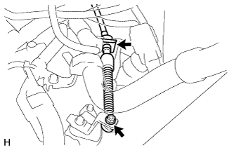
Remove the clip and nut, and disconnect the transmission control cable assembly from the No. 1 transmission control cable bracket and control shaft lever.
-
-
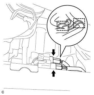
DISCONNECT FUEL TUBE SUB-ASSEMBLY
-
Remove the fuel pipe clamp.
-
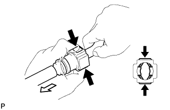
Disconnect the connector from the tube by hand. When the connector and the tube are stuck, push in and pull on the connector to release it. Pull the connector out of the tube carefully.
Text in Illustration 
Push 
Pull Note
-
Check for any dirt and foreign matter in the tube and around the connector. Clean if necessary. Foreign matter may damage the O-rings or cause leaks in the seal between the tube and connector.
-
Do not use any tools to separate the tube and connector.
-
Do not forcibly bend or twist the nylon tube.
-
Check for any dirt and foreign matter on the tube seal surface. Clean if necessary.
-
Cover the tube and connector ends with plastic bags to prevent damage and dirt contamination.
-
If the tube and connector are stuck together, pinch the tube between your fingers and turn it carefully to free it. Then disconnect the hose.
-
-
-
DISCONNECT NO. 1 COOLER REFRIGERANT DISCHARGE HOSE
-
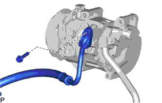
Remove the bolt and disconnect the No. 1 cooler refrigerant discharge hose from the compressor and magnetic clutch.
-
Remove the O-ring from the No. 1 cooler refrigerant discharge hose.
Note
Seal the openings of the disconnected parts using vinyl tape to prevent moisture and foreign matter from entering them.
-
-
DISCONNECT NO. 1 COOLER REFRIGERANT SUCTION HOSE
-
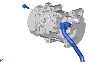
Remove the bolt and disconnect the No. 1 cooler refrigerant suction hose from the compressor and magnetic clutch.
-
Remove the O-ring from the No. 1 cooler refrigerant suction hose.
Note
Seal the openings of the disconnected parts using vinyl tape to prevent moisture and foreign matter from entering them.
-
-
REMOVE NO. 1 EXHAUST PIPE SUPPORT BRACKET
-
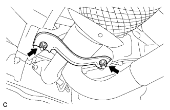
Remove the 2 nuts and No. 1 exhaust pipe support bracket (for Front Side).
-
-
REMOVE FRONT EXHAUST PIPE ASSEMBLY
-
Disconnect the 2 wire harnesses from the clamp.
-
Disconnect the 2 heated oxygen sensor connectors.
-
Remove the 2 bolts and No. 1 exhaust pipe support bracket (for Rear Side).
-
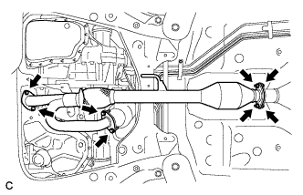
Remove the 4 bolts, 4 nuts and front exhaust pipe assembly.
-
Remove the 3 gaskets from the front exhaust pipe assembly.
-
-
SECURE STEERING WHEEL
-
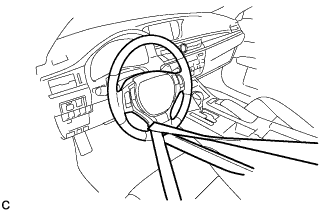
Secure the steering wheel with the seat belt in order to prevent rotation.
Tech Tips
This operation is useful to prevent damage to the spiral cable.
-
-
SEPARATE STEERING INTERMEDIATE SHAFT ASSEMBLY
-
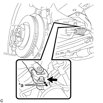
Text in Illustration *a Matchmark Put matchmarks on the steering intermediate shaft assembly and steering link assembly.
-
Remove the bolt.
-
Separate the steering intermediate shaft assembly from the steering link assembly.
-
-
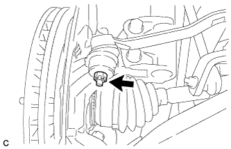
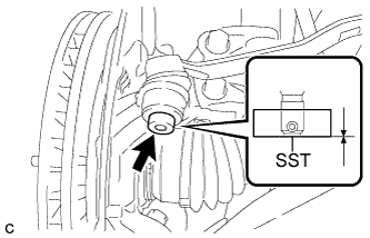
REMOVE FRONT AXLE SHAFT NUT LH
-
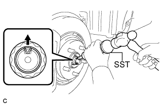
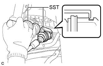
Using SST and a hammer, release the staked part of the front axle shaft nut.
- SST
- 09930-00010
Note
Loosen the staked part of the nut completely, otherwise the threads of the drive shaft may be damaged.
-
While applying the brakes, remove the front axle shaft nut.
-
-
REMOVE FRONT AXLE SHAFT NUT RH
Tech Tips
Perform the same procedure as for the LH side.
-
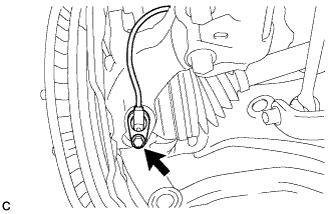
SEPARATE FRONT STABILIZER LINK ASSEMBLY LH
-
Remove the nut and separate the front stabilizer link assembly from the front shock absorber assembly.
If the ball joint turns together with the nut, use a hexagon wrench to hold the stud bolt.
-
-
SEPARATE FRONT STABILIZER LINK ASSEMBLY RH
Tech Tips
Perform the same procedure as for the LH side.
-
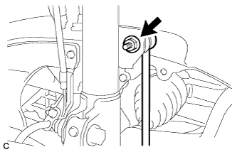
SEPARATE FRONT SPEED SENSOR LH
-
Remove the bolt, disengage the clamp and separate the front speed sensor and front flexible hose from the front shock absorber.
Note
Be sure to separate the front speed sensor from the front shock absorber completely.
-
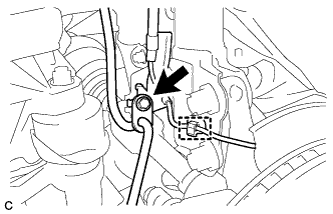
Remove the bolt and front speed sensor from the steering knuckle.
Note
-
Prevent foreign matter from contacting the sensor tip.
-
Be careful not to damage the front speed sensor.
-
Clean the speed sensor installation hole and the contact surfaces every time the speed sensor is removed.
-
-
-
SEPARATE FRONT SPEED SENSOR RH
Tech Tips
Perform the same procedure as for the LH side.
-
SEPARATE TIE ROD ASSEMBLY LH
-
Remove the cotter pin and nut.
-
Install SST to the tie rod assembly LH.
- SST
- 09960-20010 ( 09961-02060 )
Note
Make sure that the lower ends of the tie rod assembly LH and SST are aligned.
-
Secure SST using a string.
Note
Be sure to tighten the string firmly to secure SST to the steering knuckle to prevent SST from falling off.
-
Using SST, separate the tie rod assembly LH from the steering knuckle.
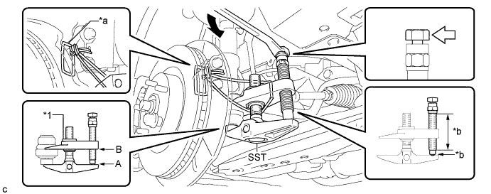
Text in Illustration *1 Center Nut - - *a String *b Molybdenum Grease Application Area Place the wrench here. - - - SST
- 09960-20010 ( 09961-02010 )
CAUTION:
Apply molybdenum grease to the bolt threads and the tip of SST.
Note
-
Make sure to tie the string of SST to the steering knuckle to prevent SST from dropping.
-
Install SST with the center nut so that A and B shown in the illustration are parallel. Otherwise, the dust cover may be damaged.
-
Be sure to place the wrench on the part indicated in the illustration.
-
Do not damage the front disc brake dust cover.
-
Do not damage the ball joint dust cover.
-
Do not damage the steering knuckle.
-
-
SEPARATE TIE ROD ASSEMBLY RH
Tech Tips
Perform the same procedure as for the LH side.
-
SEPARATE FRONT LOWER NO. 1 SUSPENSION ARM SUB-ASSEMBLY LH
-
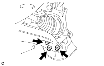
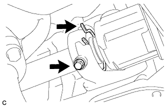
Remove the bolt and 2 nuts, and separate the front lower No. 1 suspension arm sub-assembly from the front lower ball joint assembly.
-
-
SEPARATE FRONT LOWER NO. 1 SUSPENSION ARM SUB-ASSEMBLY RH
Tech Tips
Perform the same procedure as for the LH side.
-
SEPARATE FRONT DRIVE SHAFT ASSEMBLY
-
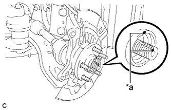
Text in Illustration *a Matchmark Put matchmarks on the front drive shaft assembly and the front axle hub sub-assembly.
-
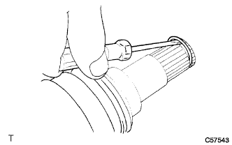
Using a plastic hammer, separate the front drive shaft assembly from the front axle assembly.
If it is difficult to separate, tap the end of the front drive shaft assembly using a brass bar and a hammer.
-
-
REMOVE FRONT DRIVE SHAFT ASSEMBLY LH
-
Using SST, remove the front drive shaft assembly LH.
- SST
- 09520-01010
- 09520-24010 ( 09520-32040 )
Note
-
Do not damage the transaxle case oil seal.
-
Do not damage the front axle inboard joint boot.
-
Do not drop the front drive shaft assembly LH.
-
-
REMOVE FRONT DRIVE SHAFT HOLE SNAP RING LH
-
Using a screwdriver, remove the front drive shaft hole snap ring LH.
-
-
REMOVE FRONT DRIVE SHAFT ASSEMBLY RH
-
Separate the bearing bracket hole snap ring from the drive shaft bearing bracket.
-
Remove the bolt and front drive shaft assembly RH from the drive shaft bearing bracket.
Note
-
Do not damage the front transaxle case oil seal.
-
Do not damage the front axle inboard joint boot.
-
Do not drop the front drive shaft assembly RH.
-
-
Remove the bearing bracket hole snap ring from the front drive shaft assembly RH.
-
-
REMOVE NO. 1 EXHAUST PIPE SUPPORT BRACKET
-
Remove the bolt and No. 1 exhaust pipe support bracket.
-
-
REMOVE NO. 1 EXHAUST PIPE SUPPORT BRACKET SUB-ASSEMBLY
-
Remove the 2 bolts and No. 1 exhaust pipe support bracket sub-assembly.
-
-
REMOVE DRIVE PLATE AND TORQUE CONVERTER ASSEMBLY SETTING BOLT
-
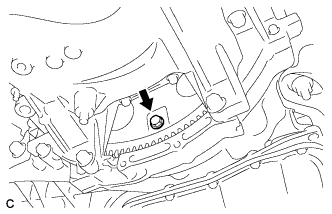
Turn the crankshaft to gain access to the 6 drive plate and torque converter assembly setting bolts and each bolt while holding the crankshaft pulley bolt with a wrench.
Tech Tips
There will be one black colored bolt.
-
-
REMOVE ENGINE ASSEMBLY WITH TRANSAXLE
-
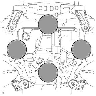
Set the engine lifter.
Text in Illustration 
Attachment Installation Position Note
-
Place the height adjustment and plate lift attachments under the engine assembly with transaxle.
-
Securely support the engine assembly to prevent it from turning upside down until it is secured to an engine stand.
-
To prevent the oil pan from deforming, do not place any attachments under the oil pan of the engine assembly with transaxle.
-
Do not perform any procedure while the engine assembly is suspended because doing so may cause the engine assembly to drop, resulting in injury. However, the engine assembly needs to be suspended when it is installed to or removed from an engine stand.
-
-
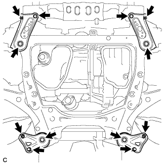
Remove the 4 bolts, 2 nuts and frame side rail plates RH and LH.
-
Remove the 4 bolts, 2 nuts and front suspension member rear braces RH and LH.
-
Operate the engine lifter, then remove the engine assembly with transaxle from the vehicle.
Note
-
Make sure that the engine assembly with transaxle is clear of all wiring and hoses.
-
While lowering the engine assembly with transaxle from the vehicle, do not allow it to contact the vehicle.
-
-
Install the engine hangers Click here.
-
-
REMOVE V-RIBBED BELT
-
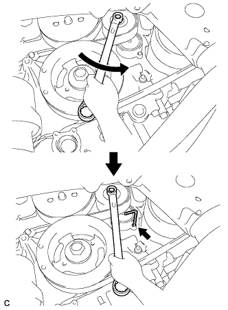
Release the V-ribbed belt tension by turning the V-ribbed belt tensioner counterclockwise, and remove the V-ribbed belt from the V-ribbed belt tensioner.
-
While turning the V-ribbed belt tensioner counterclockwise, align its holes, and then insert a 5 mm hexagon wrench into the holes to fix the V-ribbed belt tensioner.
-
-
REMOVE GENERATOR ASSEMBLY
-
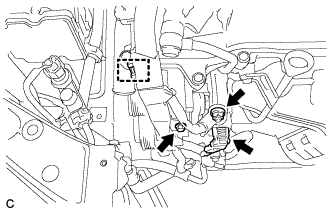
Disconnect the connector.
-
Remove the cap.
-
Remove the nut and disconnect the wire harness.
-
Remove the bolt and disconnect the wire harness clamp.
-
Remove the 2 bolts.
-
Disconnect the wire harness clamp and remove the generator bracket.
-
Remove the 2 bolts and generator assembly.
-
-
REMOVE COMPRESSOR AND MAGNETIC CLUTCH
-
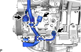
Disconnect the 3 connectors.
-
Disengage the 3 clamps.
-
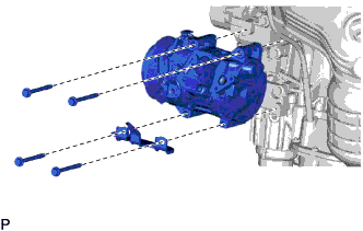
Remove the 4 bolts, compressor and magnetic clutch and bracket.
-
-
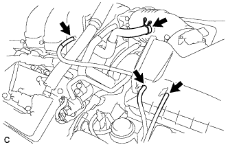
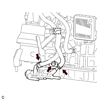
REMOVE TRANSMISSION OIL COOLER (w/ ATF Warmer)
-
w/o Transmission Oil Thermostat:
-
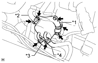
Text in Illustration *1 No. 3 Water By-pass Hose *2 No. 4 Water By-pass Hose *3 No. 1 Oil Cooler Outlet Hose *4 No. 1 Oil Cooler Inlet Hose Release the 4 clamps and disconnect the No. 3 water by-pass hose, No. 4 water by-pass hose, No. 1 oil cooler outlet hose and No. 1 oil cooler inlet hose from the transmission oil cooler.
-
-
w/ Transmission Oil Thermostat:
-
Text in Illustration *1 No. 3 Water By-pass Hose *2 No. 4 Water By-pass Hose *3 No. 1 Transmission Oil Cooler Hose Assembly *4 No. 1 Oil Cooler Inlet Hose Release the 4 clamps and disconnect the No. 3 water by-pass hose, No. 4 water by-pass hose, No. 1 transmission oil cooler hose assembly and No. 1 oil cooler inlet hose from the transmission oil cooler.
-
-
Remove the 3 bolts, transmission oil cooler and transmission oil cooler stay from the front engine mounting bracket.
-
-
REMOVE TRANSMISSION OIL THERMOSTAT (w/ ATF Warmer)
-
w/ Transmission Oil Thermostat:
-
Disconnect the inlet oil cooler hose and outlet oil cooler hose.
-
Disconnect the clamp and remove the bolt and transmission oil thermostat.
-
-
-
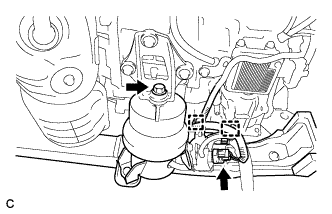
REMOVE FRONT FRAME ASSEMBLY
-
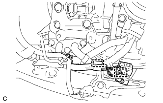
Disconnect the 2 clamps.
-
Disconnect the 2 clamps and vacuum switching valve connector.
-
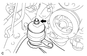
Remove the bolt and disconnect the front engine mounting insulator assembly.
-
Remove the nut and disconnect the engine mounting insulator LH.
-
Remove the nut and disconnect the engine mounting insulator RH.
-
Remove the front frame assembly.
-
-
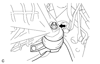
REMOVE FRONT ENGINE MOUNTING INSULATOR ASSEMBLY
-
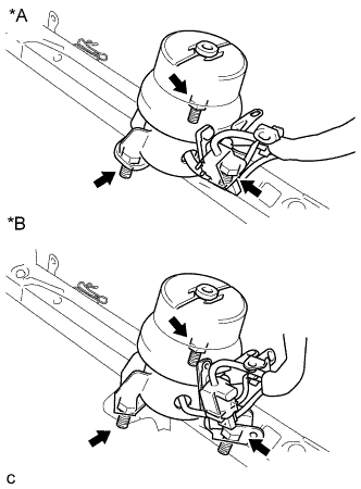
Text in Illustration *A w/o Transmission Oil Thermostat *B w/ Transmission Oil Thermostat Remove the 3 nuts and front engine mounting insulator assembly.
Tech Tips
Perform this procedure only when replacement of the front engine mounting insulator assembly is necessary.
-
-
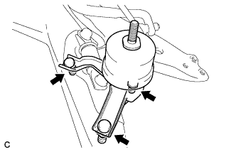
REMOVE ENGINE MOUNTING INSULATOR LH
-
Remove the 2 hole plugs from the front frame assembly.
-
Remove the 3 nuts and engine mounting insulator LH.
Tech Tips
Perform this procedure only when replacement of the engine mounting insulator LH is necessary.
-
-
REMOVE ENGINE MOUNTING INSULATOR RH
-
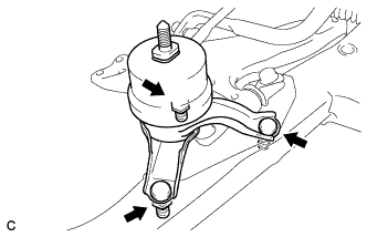
Remove the 2 hole plugs from the front frame assembly.
-
Remove the 3 nuts and engine mounting insulator RH.
Tech Tips
Perform this procedure only when replacement of the engine mounting insulator RH is necessary.
-
-
REMOVE ENGINE WIRE
-
Remove the engine wire from the engine with transaxle.
-
-
REMOVE AUTOMATIC TRANSAXLE ASSEMBLY
-
Disconnect the breather plug and remove the clamp. (w/ ATF Warmer)
-
Release the clamp and remove the No. 4 water by-pass hose from the water inlet pipe. (w/ ATF Warmer)
-
Using a transmission jack attachment, set the automatic transaxle assembly on a transmission jack.
Note
-
Secure the automatic transaxle assembly to the transmission jack using a suitable adapter, such as a rope or attachment.
-
To prevent the automatic transaxle oil pan sub-assembly from deforming, do not place any attachments onto the automatic transaxle oil pan sub-assembly of the automatic transaxle assembly.
-
Hold the engine assembly with a suitable adapter, such as a rope, during the operation.
-
-
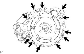
Remove the 11 bolts and automatic transaxle assembly.
Note
To prevent damage to the knock pins, do not pry between the automatic transaxle assembly and engine assembly.
-
-
REMOVE ENGINE MOUNTING BRACKET RH
-
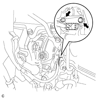
Remove the 3 bolts and engine mounting bracket RH.
-
-
REMOVE DRIVE SHAFT BEARING BRACKET
-
Remove the 3 bolts and drive shaft bearing bracket.
-
-
REMOVE DRIVE PLATE AND RING GEAR SUB-ASSEMBLY
-
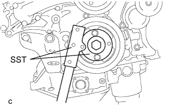
Using SST, hold the crankshaft pulley.
- SST
- 09213-70011 ( 09213-70020 )
- 09330-00021
-
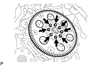
Remove the 8 bolts, front drive plate spacer, drive plate and ring gear sub-assembly and rear drive plate spacer.
-
-
INSTALL ENGINE TO ENGINE STAND
-
Install the engine to an engine stand with the bolts.
-