EXHAUST MANIFOLD INSTALLATION

-
INSTALL NO. 1 MANIFOLD CONVERTER INSULATOR
-
Install the No. 1 manifold converter insulator with the 4 bolts.
- Torque:
- 14 N*m { 138 kgf*cm, 10 ft.*lbf }
-
-
INSTALL NO. 2 EXHAUST MANIFOLD HEAT INSULATOR
-
Install the No. 2 exhaust manifold heat insulator with the 2 bolts.
- Torque:
- 14 N*m { 138 kgf*cm, 10 ft.*lbf }
-
-
INSTALL EXHAUST MANIFOLD CONVERTER SUB-ASSEMBLY
-
Set a new gasket to the cylinder head sub-assembly.
-
Temporarily install the exhaust manifold converter sub-assembly with the 5 nuts.
-
Temporarily install the No. 2 manifold stay and manifold stay with the 2 bolts and 2 nuts.
-
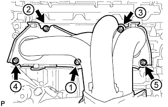
Tighten the 5 nuts in the sequence shown in the illustration.
- Torque:
- 35 N*m { 357 kgf*cm, 26 ft.*lbf }
-
-
INSTALL AIR FUEL RATIO SENSOR
-
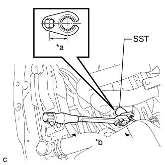
Text in Illustration *a Fulcrum Length
30 mm
*b Fulcrum Length
300 mm
Using SST, install the air fuel ratio sensor to the exhaust manifold.
- SST
- 09224-00010
- Torque:
- without SST
- 44 N*m { 449 kgf*cm, 32 ft.*lbf }
- with SST
- 40 N*m { 408 kgf*cm, 30 ft.*lbf }
Note
-
The "with SST" torque value is effective when using SST with a fulcrum length of 30 mm (1.18 in.) and a torque wrench with a fulcrum length of 300 mm (11.8 in.) Click here.
-
The "with SST" torque value is effective when SST is parallel to the torque wrench.
Tech Tips
Perform "Inspection After Repair" after replacing the air fuel ratio sensor Click here.
-
Connect the air fuel ratio sensor connector.
-
Install the hose clamp.
-
-
INSTALL NO. 1 EXHAUST MANIFOLD HEAT INSULATOR
-
Install the No. 1 exhaust manifold heat insulator with the 4 bolts.
- Torque:
- 12 N*m { 122 kgf*cm, 9 ft.*lbf }
-
-
INSTALL NO. 2 MANIFOLD STAY
-
Install the No. 2 manifold stay with the bolt and nut.
- Torque:
- 43 N*m { 438 kgf*cm, 32 ft.*lbf }
-
-
INSTALL MANIFOLD STAY
-
Install the manifold stay with the bolt and nut.
- Torque:
- 43 N*m { 438 kgf*cm, 32 ft.*lbf }
-
-
INSTALL FRONT EXHAUST PIPE ASSEMBLY
-
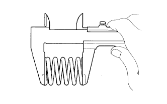
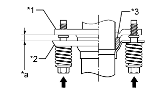
Text in Illustration *1 Exhaust Manifold Converter Sub-assembly *2 Gasket *3 Wooden Block Using a vernier caliper, measure the free length of the compression spring.
Minimum 40.5 mm (1.59 in.) Tech Tips
If the length is less than the minimum, replace the compression spring.
-
Fully insert a new gasket to the exhaust manifold converter sub-assembly.
-
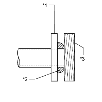
Text in Illustration *1 Exhaust Manifold Converter Sub-assembly *2 Front Exhaust Pipe Assembly *3 Gasket *a Space between flanges: 8.5 mm (0.335 in.) Using a plastic hammer and wooden block, tap in the new gasket until its surface is flush with the exhaust manifold converter sub-assembly.
Note
-
Be sure to install the gasket in the correct direction.
-
Do not reuse the gasket.
-
Do not damage the gasket.
-
Do not push in the gasket by using the exhaust pipe when connecting it.
-
-
Install a new gasket to the front exhaust pipe assembly.
-
Connect the front exhaust pipe assembly to the exhaust pipe support.
-
Install the front exhaust pipe assembly with the 2 compression springs, 2 bolts and 2 nuts.
- Torque:
- 43 N*m { 438 kgf*cm, 32 ft.*lbf }
Tech Tips
After the installation, check that the gaps between the flanges of the exhaust manifold converter sub-assembly and front exhaust pipe assembly are consistent front-to-rear and left-to-right.
-
Connect the heated oxygen sensor connector.
-
-
INSTALL ENGINE UNDER COVER RH
-
INSTALL ENGINE UNDER COVER LH
-
INSTALL FRONT WHEEL OPENING EXTENSION PAD RH
-
INSTALL FRONT WHEEL OPENING EXTENSION PAD LH
-
INSPECT FOR EXHAUST GAS LEAK