INTAKE MANIFOLD REMOVAL

-
PRECAUTION
Note
After turning the engine switch off, waiting time may be required before disconnecting the cable from the negative (-) battery terminal. Therefore, make sure to read the disconnecting the cable from the negative (-) battery terminal notice before proceeding with work Click here.
-
DISCHARGE FUEL SYSTEM PRESSURE
-
DISCONNECT CABLE FROM NEGATIVE BATTERY TERMINAL
Note
When disconnecting the cable, some systems need to be initialized after the cable is reconnected Click here.
-
DRAIN ENGINE COOLANT
CAUTION:
Do not remove the radiator cap sub-assembly, cylinder block drain cock plugs or radiator drain cock plug while the engine and radiator assembly are still hot. Pressurized, hot engine coolant and steam may be released and cause serious burns.
-
Loosen the radiator drain cock plug.
-
Loosen the cylinder block drain cock plug. (for Bank 1)
-
Loosen the cylinder block drain cock plug. (for Bank 2, w/ Cylinder Block Drain Cock Plug)
-
Remove the radiator cap sub-assembly.
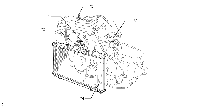
Text in Illustration *1 Radiator Cap Sub-assembly *2 Cylinder Block Drain Cock Plug (for Bank 1) *3 Cylinder Block Drain Cock Plug (for Bank 2, w/ Cylinder Block Drain Cock Plug) *4 Radiator Drain Cock Plug *5 Air Drain Cock Plug - - Tech Tips
Collect the engine coolant in a container and dispose of it according to the regulations in your area.
-
-
REMOVE WINDSHIELD WIPER MOTOR AND LINK ASSEMBLY
-
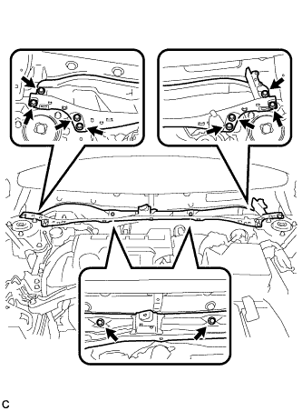
REMOVE FRONT OUTER COWL TOP PANEL SUB-ASSEMBLY (for LHD)
-
w/ Wiper Deicer System:
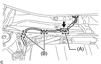
Disengage the clamp (A).
-
Disengage the 2 clamps (B).
-
Disconnect the connector and separate the wire harness from the front outer cowl top panel sub-assembly.
-
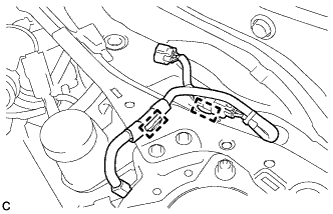
Disengage the 2 clamps and separate the wire harness from the front outer cowl top panel sub-assembly.
-
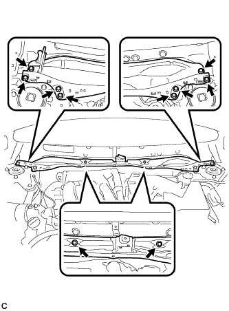
Remove the 10 bolts and front outer cowl top panel sub-assembly.
-
-
REMOVE FRONT OUTER COWL TOP PANEL SUB-ASSEMBLY (for RHD)
-
Disengage the 2 clamps and separate the wire harness from the front outer cowl top panel sub-assembly.
-
Remove the 10 bolts and front outer cowl top panel sub-assembly.
-
-
REMOVE V-BANK COVER SUB-ASSEMBLY
-
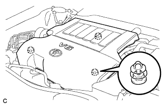
Hold the front of the V-bank cover sub-assembly and raise it to disengage the 2 retainers on the front of the V-bank cover sub-assembly. Continue to raise the V-bank cover sub-assembly to disengage the retainer on the rear of the V-bank cover sub-assembly and remove the V-bank cover sub-assembly.
Note
Attempting to disengage both front and rear retainers at the same time may cause the V-bank cover sub-assembly to break.
-
-
REMOVE AIR CLEANER CAP SUB-ASSEMBLY
-
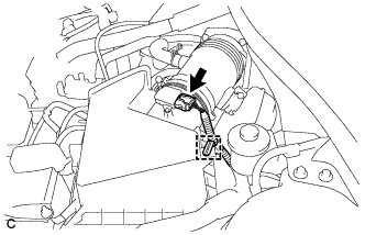
Disconnect the mass air flow meter connector and wire harness clamp.
-
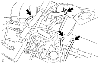
Disconnect the 3 hoses.
-
Disconnect the ventilation hose from the air cleaner cap sub-assembly.
-
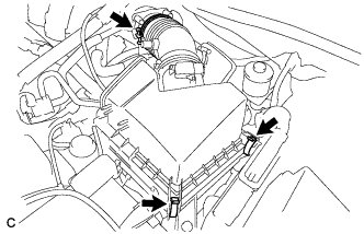
Loosen the hose clamp and separate the air cleaner cap sub-assembly from the throttle with motor body assembly.
-
Release the 2 clamps and remove the air cleaner cap sub-assembly.
-
-
REMOVE INTAKE AIR SURGE TANK ASSEMBLY
-
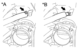
Text in Illustration *A Type A *B Type B Slide the clip and disconnect the ventilation hose from the intake air surge tank assembly.
-
for LHD:
-
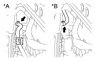
Text in Illustration *A for LHD *B for RHD Slide the clip and disconnect the union to check valve hose from the intake air surge tank assembly.
-
Disengage the hose clamp.
-
-
for RHD:
-
Slide the clip and disconnect the union to check valve hose from the intake air surge tank assembly.
-
-
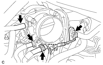
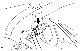
Disconnect the throttle body assembly connector.
-
Disengage the wire harness clamp.
-
Slide the 2 clips and disconnect the 2 water by-pass hoses from the throttle body assembly.
-
Disconnect the fuel vapor feed hose from the intake air surge tank assembly.
-
Disconnect the intake air control valve assembly connector.
-
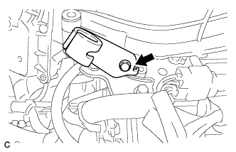
Remove the bolt and vacuum hose clamp from the throttle body bracket.
-
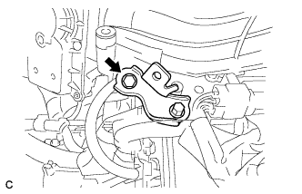
Remove the bolt and separate the throttle body bracket from the intake air surge tank assembly.
-
Remove the bolt and separate the No. 1 surge tank stay from the intake air surge tank assembly.
-
Remove the 2 nuts from the intake air surge tank assembly.
-
Using a 5 mm hexagon socket wrench, remove the 4 bolts from the intake air surge tank assembly.
-
Remove the intake air surge tank assembly and 3 gaskets.
-
-
REMOVE NO. 2 ENGINE MOUNTING STAY RH (for Engine Mounting stay Side)
-

Remove the bolt, 2 nuts and No. 2 engine mounting stay RH.
-
-
REMOVE NO. 2 ENGINE MOUNTING STAY RH (for Intake Manifold Side)
-
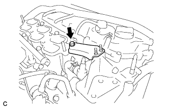
Remove the bolt and No. 2 engine mounting stay RH.
-
-
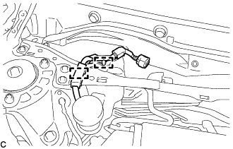
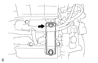
DISCONNECT FUEL TUBE SUB-ASSEMBLY
-

Text in Illustration *1 No. 2 Fuel Pipe Clamp *2 Fuel Tube Connector *3 Nylon Tube *4 O-ring *5 Fuel Pipe 
Pinch 
Pull Remove the No. 2 fuel pipe clamp.
-
Pinch the fuel tube connector and pull out the fuel pipe.
Note
-
Check for foreign matter on the fuel tube around the fuel tube connector. Clean it if necessary. Foreign matter can affect the ability of the O-ring to seal the fuel tube connector and fuel pipe.
-
Do not use any tools to separate the fuel tube connector and fuel pipe.
-
Do not forcibly bend, kink or twist the nylon tube.
-
Keep the connector and fuel pipe free from foreign matter.
-
If the fuel tube connector and fuel pipe are stuck, push and pull to release them.
-
Cover the fuel tube connector and fuel pipe with plastic bags to prevent damage and contamination.
-
-
-
REMOVE FUEL DELIVERY PIPE SUB-ASSEMBLY
-
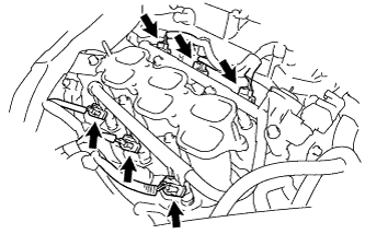
Disconnect the 6 fuel injector connectors.
-
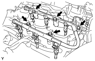
Remove the 5 bolts and fuel delivery pipe sub-assembly together with the 6 fuel injector assemblies.
Note
Be careful not to drop the fuel injector assemblies when removing the fuel delivery pipe sub-assembly.
-
Remove the 6 injector vibration insulators from the intake manifold.
-
-
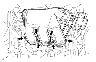
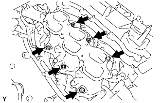
REMOVE INTAKE MANIFOLD
-
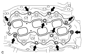
Remove the 6 bolts, 4 nuts and intake manifold from the cylinder head sub-assembly.
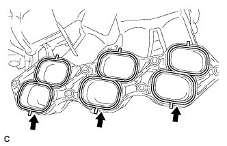
-
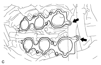
Remove the 2 gaskets from each cylinder head sub-assembly.
-