VEHICLE PROXIMITY NOTIFICATION SYSTEM The Sound does not Stop when The Engine is Operated or when The Shift Lever is in P
DESCRIPTION
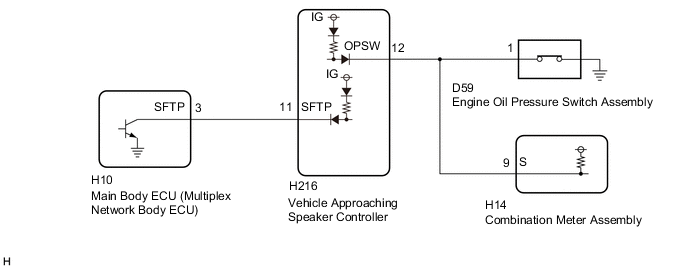
The vehicle approaching speaker controller receives engine oil pressure switch signals from the engine oil pressure switch assembly and P position switch signals from the main body ECU (multiplex network body ECU), and produces the warning sound from the vehicle approaching speaker assembly.
WIRING DIAGRAM
PROCEDURE
-
READ VALUE USING GTS (Oil Pressure SW)
-
Connect the GTS to the DLC3.
-
Turn the power switch on (IG).
-
Turn the GTS on.
-
Enter the following menus: Body Electrical / Vehicle Proximity Notification System / Data List.
-
Read the Data List according to the display on the GTS.
Vehicle Proximity Notification System Tester Display Measurement Item/Range Normal Condition Diagnostic Note Oil Pressure SW Oil pressure switch condition / OFF or ON OFF: Engine started
ON: Engine not started
- Result Result Proceed to The GTS display changes according to engine operation A The GTS display does not change according to engine operation B
B 
CHECK ENGINE OIL PRESSURE SWITCH ASSEMBLY Click here
A 
-
-
READ VALUE USING GTS (Shift Position)
-
Connect the GTS to the DLC3.
-
Turn the power switch on (IG).
-
Turn the GTS on.
-
Enter the following menus: Body Electrical / Vehicle Proximity Notification System / Data List.
-
Read the Data List according to the display on the GTS.
Vehicle Proximity Notification System Tester Display Measurement Item/Range Normal Condition Diagnostic Note Shift Position P position switch / Not Parking or Parking Not Parking: Shift lever is not in P
Parking: Shift lever is in P
- Result Result Proceed to The GTS display changes according to the shift lever position A The GTS display does not change according to the shift lever position B
A 
REPLACE VEHICLE APPROACHING SPEAKER CONTROLLER Click here
B
-
-
CHECK VEHICLE APPROACHING SPEAKER CONTROLLER
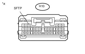
*a Front view of wire harness connector
(to Main Body ECU (Multiplex Network Body ECU))
-
Disconnect the H10 main body ECU (multiplex network body ECU) connector.
-
Measure the voltage according to the value(s) in the table below.
Standard Voltage Tester Connection Condition Specified Condition H10-3 (SFTP) - Body ground Power switch on (IG) 11 to 14 V Power switch off Below 1 V Result Result OK NG
NG
CHECK HARNESS AND CONNECTOR (MAIN BODY ECU (MULTIPLEX NETWORK BODY ECU) - VEHICLE APPROACHING SPEAKER CONTROLLER) Click here
OK
-
-
CHECK MAIN BODY ECU (MULTIPLEX NETWORK BODY ECU)
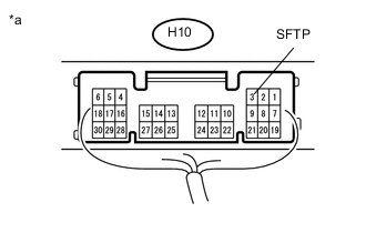
*a Component with harness connected
(Main Body ECU (Multiplex Network Body ECU))
-
Reconnect the H10 main body ECU (multiplex network body ECU) connector.
-
Measure the voltage according to the value(s) in the table below.
Standard Voltage Tester Connection Condition Specified Condition H10-3 (SFTP) - Body ground Power switch on (IG), shift lever in P Below 2.5 V Power switch on (IG), shift lever not in P 8 V or higher Result Result OK NG
OK
REPLACE VEHICLE APPROACHING SPEAKER CONTROLLER Click here
NG
REPLACE MAIN BODY ECU (MULTIPLEX NETWORK BODY ECU) Click here
-
-
CHECK HARNESS AND CONNECTOR (MAIN BODY ECU (MULTIPLEX NETWORK BODY ECU) - VEHICLE APPROACHING SPEAKER CONTROLLER)
-
Disconnect the H216 vehicle approaching speaker controller connector.
-
Measure the resistance according to the value(s) in the table below.
Standard Resistance Tester Connection Condition Specified Condition H10-3 (SFTP) - H216-11 (SFTP) Always Below 1 Ω H10-3 (SFTP) or H216-11 (SFTP) - Body ground Always 10 kΩ or higher Result Proceed to OK NG
OK
REPLACE VEHICLE APPROACHING SPEAKER CONTROLLER Click here
NG
REPAIR OR REPLACE HARNESS OR CONNECTOR
-
-
CHECK ENGINE OIL PRESSURE SWITCH ASSEMBLY
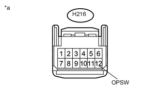
*a Front view of wire harness connector
(to Vehicle Approaching Speaker Controller)
-
Disconnect the H216 vehicle approaching speaker controller connector.
-
Measure the voltage according to the value(s) in the table below.
Standard Voltage Tester Connection Condition Specified Condition H216-12 (OPSW) - Body ground Idling* 8 V or higher Power switch on (IG) Below 2 V Result Result OK NG
OK
REPLACE VEHICLE APPROACHING SPEAKER CONTROLLER Click here
NG
-
-
CHECK HARNESS AND CONNECTOR (VEHICLE APPROACHING SPEAKER CONTROLLER - ENGINE OIL PRESSURE SWITCH ASSEMBLY)
-
Disconnect the D59 engine oil pressure switch assembly connector.
-
Measure the resistance according to the value(s) in the table below.
Standard Resistance Tester Connection Condition Specified Condition H216-12 (OPSW) - D59-1 Always Below 1 Ω H216-12 (OPSW) or D59-1 - Body ground Always 10 kΩ or higher Result Proceed to OK NG
NG
REPAIR OR REPLACE HARNESS OR CONNECTOR
OK
-
-
INSPECT ENGINE OIL PRESSURE SWITCH ASSEMBLY
-
Remove the engine oil pressure switch assembly.
-
Inspect the engine oil pressure switch assembly.
Result Proceed to OK NG
OK
USE SIMULATION METHOD TO CHECK Click here
NG
REPLACE ENGINE OIL PRESSURE SWITCH ASSEMBLY Click here
-