PROCEDURE
- Click here
INSPECT MULTI-MEDIA MODULE RECEIVER ASSEMBLY (HAZARD SWITCH) (for Navigation Receiver Type)
-
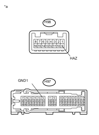
Measure the resistance according to the value(s) in the table below.
Standard Resistance Tester Connection Condition Specified Condition H98-9 (HAZ) - H97-12 (GND1) Hazard switch off 10 kΩ or higher Hazard switch on Below 1 Ω Table 1. Text in Illustration *a Component without harness connected
(Multi-media Module Receiver Assembly (Hazard Switch))
If the result is not as specified, replace the multi-media module receiver assembly.
-
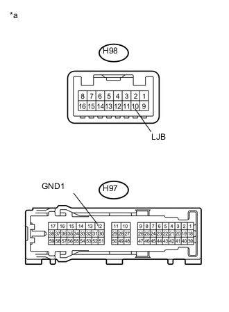
Illumination Inspection
-
Apply auxiliary battery voltage to the multi-media module receiver assembly and check that the hazard switch illuminates.
OK Condition Specified Condition Auxiliary battery positive (+) → H98-10 (LJB)
Auxiliary battery negative (-) → H97-12 (GND1)
Illuminates Table 2. Text in Illustration *a Component without harness connected
(Multi-media Module Receiver Assembly (Hazard Switch))
If the result is not as specified, replace the multi-media module receiver assembly.
-
-
- Click here
INSPECT RADIO RECEIVER ASSEMBLY (HAZARD SWITCH) (for Radio Receiver Type)
-
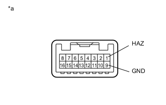
Measure the resistance according to the value(s) in the table below.
Standard Resistance Tester Connection Condition Specified Condition 1 (HAZ) - 9 (GND) Hazard switch off 10 kΩ or higher Hazard switch on Below 1 Ω Table 3. Text in Illustration *a Component without harness connected
(Radio Receiver Assembly (Hazard Switch))
If the result is not as specified, replace the radio receiver assembly.
-
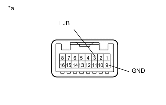
Illumination Inspection
-
Apply auxiliary battery voltage to the radio receiver assembly and check that the hazard switch illuminates.
OK Condition Specified Condition Auxiliary battery positive (+) → Terminal 3 (LJB)
Auxiliary battery negative (-) → Terminal 9 (GND)
Illuminates Table 4. Text in Illustration *a Component without harness connected
(Radio Receiver Assembly (Hazard Switch))
If the result is not as specified, replace the radio receiver assembly.
-
-