HEADLIGHT ASSEMBLY REASSEMBLY
PROCEDURE
-
INSTALL HEADLIGHT UNIT
-
Install the headlight unit to the housing with the 3 screws.
-
Connect the connector.
-
-
INSTALL HEADLIGHT LENS GASKET
-
Completely remove the old headlight lens gasket.
-
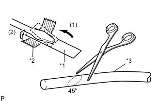
Text in Illustration *1 Release Paper *2 Tape *3 Headlight Lens Gasket Partially remove the release paper from a new headlight lens gasket, and cut off a piece of it.
-
Fold the release paper over the tip of a screwdriver and fix it in place with tape.
Tech Tips
Use the release paper that is supplied with the headlight lens gasket.
-
Using scissors, cut the end of the headlight lens gasket at an angle (45°).
-
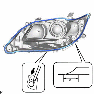
Set the headlight lens gasket into the groove so that the ends of the gasket are aligned with the bottom of the housing, as shown in the illustration.
Standard Dimension Area Dimension a 10 mm (0.394 in.) or more -
Using the screwdriver, completely press the headlight lens gasket into the housing to install it.
-
After pressing the headlight lens gasket completely, check that the ends overlap for 10 mm (0.394 in.) or more.
Tech Tips
Place the headlight lens gasket along the outside surface and press it in with the screwdriver to roll it into place. Then, set the headlight lens gasket at the center of the groove.
-
-
INSTALL HEADLIGHT LENS
-
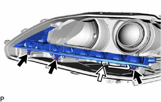
Engage the 9 claws to temporary install the headlight lens to the housing.
Note
-
Check that all the claws are engaged.
-
Wear rubber gloves when handling the headlight lens.
-
Do not touch the lens or the aluminum surfaces with bare hands.
-
If there are fingerprints on the aluminum surfaces, wipe them off with a soft cloth.
-
If there are fingerprints on the back of the headlight lens, replace the headlight lens.
-
Do not allow dirt or foreign matter to get on the headlight lens.
-
-
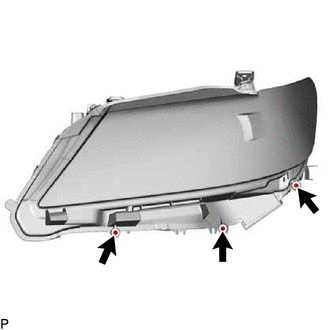
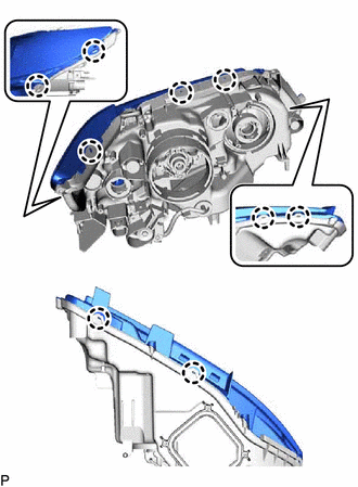
Install the 3 screws.
-
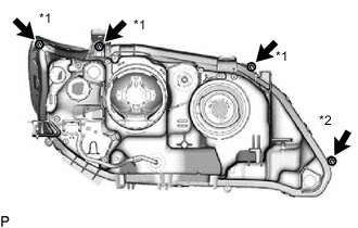
Text in Illustration *1 Screw *2 "TORX" Screw Using a T20H "TORX" driver, install the "TORX" screw.
-
Install the 3 screws to install the headlight lens.
-
-
INSTALL HEADLIGHT LEVELING MOTOR BASE PACKING
-
Install a new headlight leveling motor base packing.
-
-
INSTALL HEADLIGHT LEVELING MOTOR
-
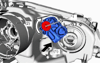
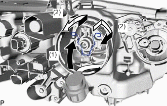
Insert the headlight leveling motor in the direction indicated by the arrow (1) shown in the illustration.
-
Turn the aiming screw of the headlight leveling motor in the direction indicated by the arrow (2) shown in the illustration to engage the shaft.
Text in Illustration *1 Aiming Screw Tech Tips
Turn the aiming screw the same number of times as it was turned during removal.
-
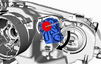
Turn the headlight leveling motor in the direction indicated by the arrow (3) shown in the illustration to install the headlight leveling motor to the headlight assembly.
Tech Tips
When installing the headlight leveling motor of the headlight assembly RH, turn the headlight leveling motor in the opposite direction of the arrow (3) shown in the illustration.
-
Turn the aiming screw of the headlight leveling motor in the direction indicated by the arrow (4) shown in the illustration to install it.
Text in Illustration *1 Aiming Screw Tech Tips
Turn the aiming screw the same number of times as it was turned during removal.
-
Engage the guide.
-
Install the bracket with the screw.
-
-
INSTALL FRONT TURN SIGNAL LIGHT BULB
-
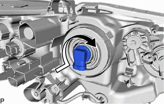
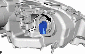
Install the front turn signal light bulb to the front turn signal light socket.
-
Turn the front turn signal light socket with the front turn signal light bulb in the direction indicated by the arrow shown in the illustration and install them as a unit.
-
-
INSTALL HEADLIGHT GASKET (for HID Headlight)
-
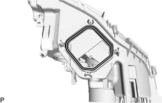
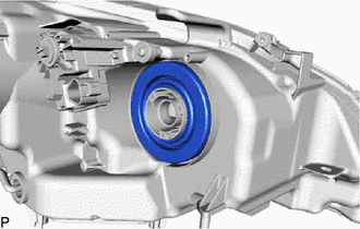
Install a new headlight gasket.
-
-
INSTALL HEADLIGHT LIGHT CONTROL ECU SUB-ASSEMBLY (for HID Headlight)
-
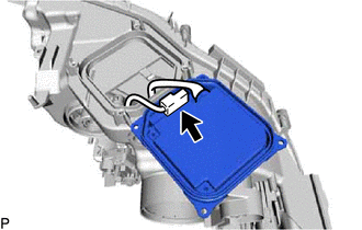
Connect the connector.
-
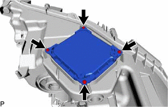
Install the headlight light control ECU sub-assembly to the headlight assembly with the 4 screws.
-
-
INSTALL HEADLIGHT SOCKET COVER
-
Install the headlight socket cover to the headlight assembly.
-
Install the socket fixture with the 3 screws.
-
for Halogen Headlight:
-
Install the headlight socket cover to the headlight assembly.
-
-
-
INSTALL NO. 2 HEADLIGHT BULB (for Halogen Headlight)
-
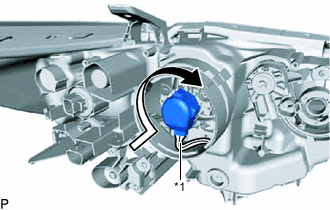
Turn the No. 2 headlight bulb in the direction indicated by the arrow shown in the illustration to install it.
Note
Do not touch the bulb glass.
-
-
INSTALL DISCHARGE HEADLIGHT BULB (for HID Headlight)
-
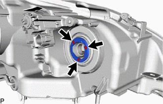
Insert the discharge headlight bulb into the headlight assembly.
Note
Do not touch the bulb glass.
-
Lock the set spring to install the discharge headlight bulb as shown in the illustration.
-
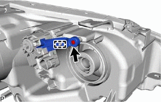
Text in Illustration *1 Red Line Turn the socket of the headlight light control ECU sub-assembly in the direction indicated by the arrow shown in the illustration to connect it.
Note
-
Check that the O-ring is installed on the headlight light control ECU socket.
-
Check that the O-ring is not damaged or contaminated with foreign matter. If there is any damage, replace the O-ring with a new one.
-
Do not pull the headlight light control ECU sub-assembly with the socket connected.
-
-
Check that the red line on the output harness is not twisted and store the harness in the headlight assembly securely so that the output harness is not pinched.
-
-
INSTALL NO. 1 HEADLIGHT COVER (for HID Headlight)
-
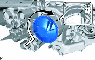
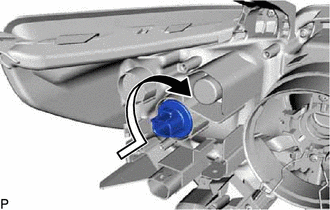
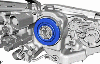
Text in Illustration *1 Lock Mark Turn the No. 1 headlight cover in the direction indicated by the arrow shown in the illustration until the lock marks are aligned to install it.
Note
-
To prevent incomplete installation, make sure to fully push in and turn the No. 1 headlight cover until the lock marks are aligned.
-
Do not apply excessive force using a tool.
-
-
-
INSTALL NO. 1 HEADLIGHT BULB
-
Turn the No. 1 headlight bulb in the direction indicated by the arrow shown in the illustration to install it.
Note
Do not touch the bulb glass.
-
-
INSTALL HEADLIGHT CORD
-
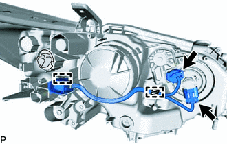
Engage the 2 clamps.
-
Connect the 2 connectors to install the headlight cord to the headlight assembly.
-