AUTOMATIC HEADLIGHT BEAM LEVEL CONTROL SYSTEM Headlight Signal Circuit
DESCRIPTION
The headlight leveling ECU assembly detects the status of the low beam headlights.
WIRING DIAGRAM
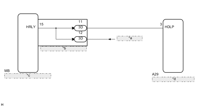
| *a | from H-LP Relay |
| *b | Instrument Panel Junction Block Assembly |
| *c | Main Body ECU (Multiplex Network Body ECU) |
| *d | Headlight Leveling ECU Assembly |
CAUTION / NOTICE / HINT
Note
First check that the low beam headlights operate normally.
PROCEDURE
-
READ VALUE USING GTS
-
Connect the GTS to the DLC3.
-
Turn the power switch on (IG).
-
Turn the GTS on.
-
Enter the following menus: Body Electrical / HL Auto Leveling / Data List.
-
Read the display on the GTS.
HL Auto Leveling Tester Display Measurement Item/Range Normal Condition Diagnostic Note Headlight Low Beam State Low beam headlight state/ON or OFF ON: Low beam headlights on
OFF: Low beam headlights off
- OK Normal conditions listed above are displayed.
OK 
PROCEED TO NEXT SUSPECTED AREA SHOWN IN PROBLEM SYMPTOMS TABLE Click here
NG 
-
-
CHECK HARNESS AND CONNECTOR (INSTRUMENT PANEL JUNCTION BLOCK ASSEMBLY - HEADLIGHT LEVELING ECU ASSEMBLY)
-
Disconnect the 3D instrument panel junction block assembly connector.
-
Disconnect the A29 headlight leveling ECU assembly connector.
-
Measure the resistance according to the value(s) in the table below.
Standard Resistance Tester Connection Condition Specified Condition 3D-11 - A29-3 (HDLP) Always Below 1 Ω 3D-11 - Body ground Always 10 kΩ or higher
NG
REPAIR OR REPLACE HARNESS OR CONNECTOR
OK
-
-
INSPECT INSTRUMENT PANEL JUNCTION BLOCK ASSEMBLY
-
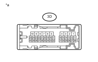
Text in Illustration *a Component without harness connected
(Instrument Panel Junction Block Assembly)
Remove the instrument panel junction block assembly Click here.
-
Measure the resistance according to the value(s) in the table below.
Standard Resistance Tester Connection Condition Specified Condition 3D-11 - 3D-12 Always Below 1 Ω 3D-11 - Body ground Always 10 kΩ or higher
OK
REPLACE HEADLIGHT LEVELING ECU ASSEMBLY Click here
NG
REPLACE INSTRUMENT PANEL JUNCTION BLOCK ASSEMBLY Click here
-