LIGHTING SYSTEM Back-up Light Circuit
DESCRIPTION
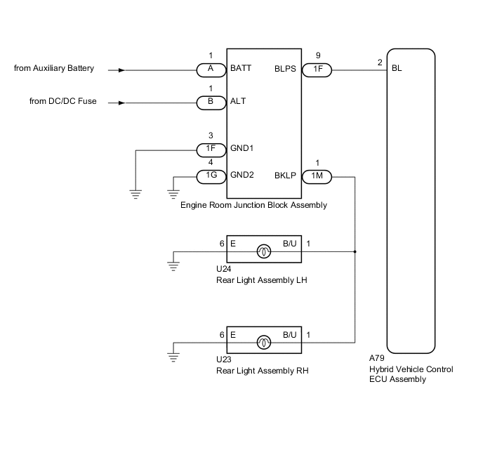
The hybrid vehicle control ECU assembly controls the back-up lights via the engine room junction block assembly.
WIRING DIAGRAM
CAUTION / NOTICE / HINT
Note
Inspect the fuses for circuits related to this system before performing the following inspection procedure.
PROCEDURE
-
CHECK DTC OUTPUT (HYBRID CONTROL SYSTEM)
-
Check for DTCs Click here.
OK Hybrid Control System DTCs are not output.
NG 
GO TO HYBRID CONTROL SYSTEM Click here
OK 
-
-
CHECK ENGINE ROOM JUNCTION BLOCK ASSEMBLY
-
Using a voltmeter, check the signal reading of the engine room junction block assembly Click here
OK Output signal reading is normal.
NG
INSPECT ENGINE ROOM JUNCTION BLOCK ASSEMBLY (RESULTS OF SIGNAL READING CHECK) Click here
OK
-
-
CHECK HARNESS AND CONNECTOR (ENGINE ROOM JUNCTION BLOCK ASSEMBLY POWER SOURCE AND BODY GROUND)
-
Remove the engine room junction block assembly from the engine room relay block and junction block assembly Click here.
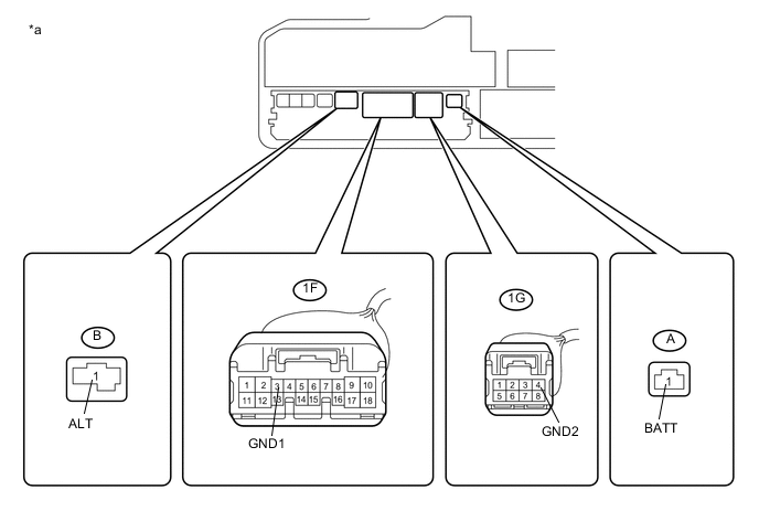
Text in Illustration *a Component without engine room junction block assembly connected
(Engine Room Relay Block and Junction Block Assembly)
- - -
Measure the voltage according to the value(s) in the table below.
Standard Voltage Tester Connection Condition Specified Condition A-1 (BATT) - Body ground Power switch off 11 to 14 V B-1 (ALT) - Body ground Power switch off 11 to 14 V -
Measure the resistance according to the value(s) in the table below.
Standard Resistance Tester Connection Condition Specified Condition 1F-3 (GND1) - Body ground Always Below 1 Ω 1G-4 (GND2) - Body ground Always Below 1 Ω
NG
REPAIR OR REPLACE HARNESS OR CONNECTOR
OK
-
-
CHECK HARNESS AND CONNECTOR (REAR LIGHT ASSEMBLY - ENGINE ROOM JUNCTION BLOCK ASSEMBLY)
-
Disconnect the U24 rear light assembly LH connector.
-
Disconnect the U23 rear light assembly RH connector.
-
Measure the resistance according to the value(s) in the table below.
Standard Resistance Tester Connection Condition Specified Condition 1M-1 (BKLP) - U24-1 (B/U) Always Below 1 Ω 1M-1 (BKLP) - U23-1 (B/U) Always Below 1 Ω
NG
REPAIR OR REPLACE HARNESS OR CONNECTOR
OK
-
-
CHECK HARNESS AND CONNECTOR (HYBRID VEHICLE CONTROL ECU ASSEMBLY - ENGINE ROOM JUNCTION BLOCK ASSEMBLY)
-
Disconnect the A79 hybrid vehicle control ECU assembly connector.
-
Measure the resistance according to the value(s) in the table below.
Standard Resistance Tester Connection Condition Specified Condition 1F-9 (BLPS) - A79-2 (BL) Always Below 1 Ω 1F-9 (BLPS) - Body ground Always 10 kΩ or higher
NG
REPAIR OR REPLACE HARNESS OR CONNECTOR
OK
-
-
CHECK ENGINE ROOM JUNCTION BLOCK ASSEMBLY
-
Replace the engine room junction block assembly with a new or known good one Click here.
OK The back-up lights operate normally.
OK
END (ENGINE ROOM JUNCTION BLOCK ASSEMBLY WAS DEFECTIVE)
NG
REPLACE HYBRID VEHICLE CONTROL ECU ASSEMBLY Click here
-