| DTC Code | DTC Name |
|---|---|
| Back-up Light Circuit |
DESCRIPTION
The power management control ECU controls the back-up lights via the engine room junction block assembly.
CAUTION / NOTICE / HINT
Inspect the fuses and bulbs for circuits related to this system before performing the following inspection procedure.
PROCEDURE
- Click here
CHECK DTC OUTPUT (HYBRID CONTROL SYSTEM)
-
Check for DTCs (Click here).
OK Hybrid Control System DTCs are not output.
- OKClick here
- NG
GO TO HYBRID CONTROL SYSTEM (Click here)
-
- Click here
CHECK ENGINE ROOM JUNCTION BLOCK ASSEMBLY
-
Using a voltmeter, check the signal reading of the engine room junction block assembly (Click here).
OK Output signal reading is normal.
- OKClick here
- NG
INSPECT ENGINE ROOM JUNCTION BLOCK ASSEMBLY (RESULTS OF SIGNAL READING CHECK) (Click here)
-
- Click here
CHECK HARNESS AND CONNECTOR (ENGINE ROOM JUNCTION BLOCK ASSEMBLY POWER SOURCE AND BODY GROUND)
-
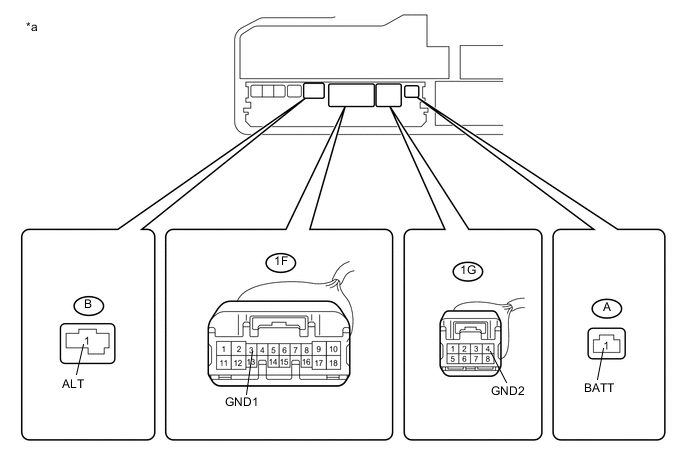
Remove the engine room junction block assembly from the engine room relay block and junction block assembly (Click here).
Table 1. Text in Illustration *a Component without engine room junction block assembly connected
(Engine Room Relay Block and Junction Block Assembly)
- - -
Measure the voltage according to the value(s) in the table below.
Standard Voltage Tester Connection Condition Specified Condition A-1 (BATT) - Body ground Power switch off 11 to 14 V B-1 (ALT) - Body ground Power switch off 11 to 14 V -
Measure the resistance according to the value(s) in the table below.
Standard Resistance Tester Connection Condition Specified Condition 1F-3 (GND1) - Body ground Always Below 1 Ω 1G-4 (GND2) - Body ground Always Below 1 Ω
- OKClick here
- NG
REPAIR OR REPLACE HARNESS OR CONNECTOR
-
- Click here
CHECK HARNESS AND CONNECTOR (REAR LIGHT ASSEMBLY - ENGINE ROOM JUNCTION BLOCK ASSEMBLY)
-
Disconnect the U7 rear light assembly LH connector.
-
Disconnect the U1 rear light assembly RH connector.
-
Measure the resistance according to the value(s) in the table below.
Standard Resistance Tester Connection Condition Specified Condition 1M-1 (BKLP) - U7-1 (B/U) Always Below 1 Ω 1M-1 (BKLP) - U1-1 (B/U) Always Below 1 Ω
- OKClick here
- NG
REPAIR OR REPLACE HARNESS OR CONNECTOR
-
- Click here
CHECK HARNESS AND CONNECTOR (POWER MANAGEMENT CONTROL ECU - ENGINE ROOM JUNCTION BLOCK ASSEMBLY)
-
Disconnect the A31 power management control ECU connector.
-
Measure the resistance according to the value(s) in the table below.
Standard Resistance Tester Connection Condition Specified Condition 1F-9 (BLPS) - A31-15 (BL) Always Below 1 Ω 1F-9 (BLPS) - Body ground Always 10 kΩ or higher
- OKClick here
- NG
REPAIR OR REPLACE HARNESS OR CONNECTOR
-
- Click here
CHECK ENGINE ROOM JUNCTION BLOCK ASSEMBLY
-
Replace the engine room junction block assembly with a new or known good one (Click here).
OK The back-up lights operate normally.
- OK
END (ENGINE ROOM JUNCTION BLOCK ASSEMBLY WAS DEFECTIVE)
- NG
REPLACE POWER MANAGEMENT CONTROL ECU (Click here)
-