| DTC Code | DTC Name |
|---|---|
| Rear Fog Light Circuit |
DESCRIPTION
The main body ECU (multiplex network body ECU) controls the rear fog lights via the engine room junction block assembly.
CAUTION / NOTICE / HINT
-
Inspect the fuses for circuits related to this system before performing the following inspection procedure.
-
If the main body ECU (multiplex network body ECU) is replaced, refer to Service Bulletin.
PROCEDURE
- Click here
CHECK OPERATION (TAILLIGHTS)
-
Check the operation of the taillights.
OK Taillights operate normally.
- OKClick here
- NG
GO TO PROBLEM SYMPTOMS TABLE (Click here)
-
- Click here
PERFORM ACTIVE TEST USING GTS
-
Connect the GTS to the DLC3.
-
Turn the power switch on (IG).
-
Turn the GTS on.
-
Enter the following menus: Body Electrical / Main Body / Active Test.
-
Check that the relay operates.
Table 1. Main Body Tester Display Test Part Control Range Diagnostic Note Rear Fog Light Relay Rear fog light relay ON/OFF Light control switch is in tail position OK Rear fog light relay operates. (Rear fog lights come on.)
- OK
PROCEED TO NEXT SUSPECTED AREA SHOWN IN PROBLEM SYMPTOMS TABLE (Click here)
- NGClick here
-
- Click here
CHECK ENGINE ROOM JUNCTION BLOCK ASSEMBLY
-
Using a voltmeter, check the signal reading of the engine room junction block assembly (Click here).
OK Output signal reading is normal.
- OKClick here
- NG
INSPECT ENGINE ROOM JUNCTION BLOCK ASSEMBLY (RESULTS OF SIGNAL READING CHECK) (Click here)
-
- Click here
CHECK HARNESS AND CONNECTOR (ENGINE ROOM JUNCTION BLOCK ASSEMBLY POWER SOURCE AND BODY GROUND)
-
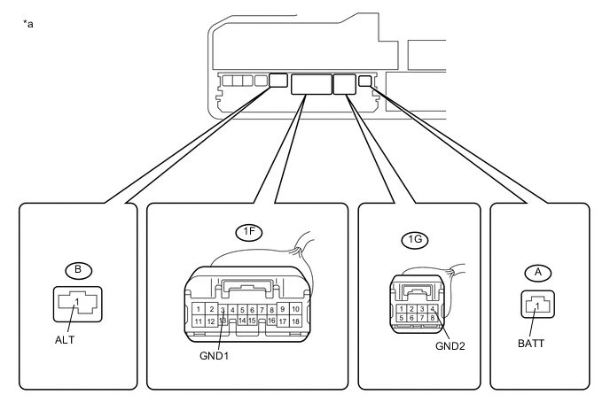
Remove the engine room junction block assembly from the engine room relay block and junction block assembly (Click here).
Table 2. Text in Illustration *a Component without engine room junction block assembly connected
(Engine Room Relay Block and Junction Block Assembly)
- - -
Measure the voltage according to the value(s) in the table below.
Standard Voltage Tester Connection Condition Specified Condition A-1 (BATT) - Body ground Power switch off 11 to 14 V B-1 (ALT) - Body ground Power switch off 11 to 14 V -
Measure the resistance according to the value(s) in the table below.
Standard Resistance Tester Connection Condition Specified Condition 1F-3 (GND1) - Body ground Always Below 1 Ω 1G-4 (GND2) - Body ground Always Below 1 Ω
- OKClick here
- NG
REPAIR OR REPLACE HARNESS OR CONNECTOR
-
- Click here
CHECK HARNESS AND CONNECTOR (INSTRUMENT PANEL JUNCTION BLOCK ASSEMBLY - ENGINE ROOM JUNCTION BLOCK ASSEMBLY)
-
Disconnect the 3D instrument panel junction block assembly connector.
-
Measure the resistance according to the value(s) in the table below.
Standard Resistance Tester Connection Condition Specified Condition 1G-2 (TAIL) - 3D-9 Always Below 1 Ω 3D-9 - Body ground Always 10 kΩ or higher 1F-10 (RFGS) - 3D-35 Always Below 1 Ω 3D-35 - Body ground Always 10 kΩ or higher
- OKClick here
- NG
REPAIR OR REPLACE HARNESS OR CONNECTOR
-
- Click here
INSPECT INSTRUMENT PANEL JUNCTION BLOCK ASSEMBLY
-
Remove the instrument panel junction block assembly (Click here).
-
Remove the main body ECU (multiplex network body ECU) from the instrument panel junction block assembly.
-
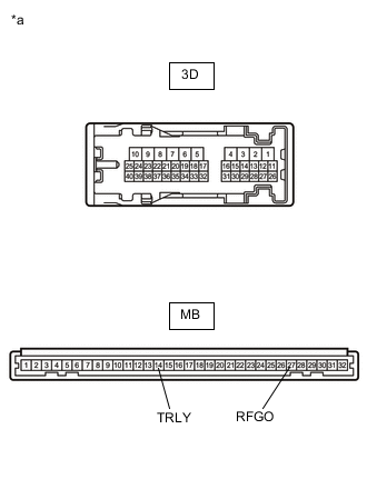
Measure the resistance according to the value(s) in the table below.
Standard Resistance Tester Connection Condition Specified Condition MB-27 (RFGO) - 3D-35 Always Below 1 Ω 3D-35 - Body ground Always 10 kΩ or higher -
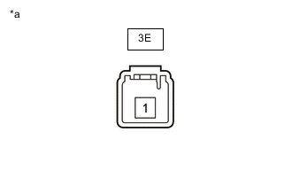
Connect a positive (+) lead from the auxiliary battery to terminal 3E-1.
-
Connect a negative (-) lead from the auxiliary battery to terminal MB-14 (TRLY).
-
Measure the voltage according to the value(s) in the table below.
Standard Voltage Tester Connection Condition Specified Condition 3D-9 - Body ground Always 11 to 14 V Table 3. Text in Illustration *a Component without harness connected
(Instrument Panel Junction Block Assembly)
- OKClick here
- NG
REPLACE INSTRUMENT PANEL JUNCTION BLOCK ASSEMBLY (Click here)
-
- Click here
CHECK HARNESS AND CONNECTOR (ENGINE ROOM JUNCTION BLOCK ASSEMBLY - REAR LIGHT ASSEMBLY)
-
Disconnect the 1F engine room junction block assembly connector.
-
Disconnect the U7 rear light assembly LH connector.
-
Disconnect the U1 rear light assembly RH connector.
-
Measure the resistance according to the value(s) in the table below.
Standard Resistance Tester Connection Condition Specified Condition 1F-12 (RFOG) - U7-3 Always Below 1 Ω 1F-12 (RFOG) - U1-3 Always Below 1 Ω
- OKClick here
- NG
REPAIR OR REPLACE HARNESS OR CONNECTOR
-
- Click here
CHECK HARNESS AND CONNECTOR (REAR LIGHT ASSEMBLY - BODY GROUND)
-
Measure the resistance according to the value(s) in the table below.
Standard Resistance Tester Connection Condition Specified Condition U7-4 - Body ground Always Below 1 Ω U1-4 - Body ground Always Below 1 Ω
- OKClick here
- NG
REPAIR OR REPLACE HARNESS OR CONNECTOR
-
- Click here
CHECK ENGINE ROOM JUNCTION BLOCK ASSEMBLY
-
Replace the engine room junction block assembly with a new or known good one (Click here).
-
Check that the fog lights operate normally.
OK The fog lights operate normally.
- OK
END (ENGINE ROOM JUNCTION BLOCK ASSEMBLY WAS DEFECTIVE)
- NG
REPLACE MAIN BODY ECU (MULTIPLEX NETWORK BODY ECU) (Click here)
-