WIPER AND WASHER SYSTEM Headlight Cleaner Switch Circuit
DESCRIPTION
This circuit detects the conditions (on or off) of the headlight cleaner switch assembly.
WIRING DIAGRAM
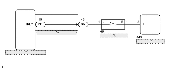
| *a | Instrument Panel Junction Block Assembly |
| *b | Headlight Cleaner Switch Assembly |
| *c | Headlight Cleaner Control Relay |
| *d | Main Body ECU (Multiplex Network Body ECU) |
CAUTION / NOTICE / HINT
Note
If the main body ECU (multiplex network body ECU) is replaced, refer to Service Bulletin.
PROCEDURE
-
INSPECT HEADLIGHT CLEANER CONTROL RELAY
-
Disconnect the A43 headlight cleaner control relay connector.
-
Measure the voltage according to the value(s) in the table below.
Standard Voltage Tester Connection Condition Specified Condition A43-2 (H) - Body ground Light control switch off and headlight cleaner switch on 11 to 14 V A43-2 (H) - Body ground Headlight cleaner switch off Below 1 V
OK 
PROCEED TO NEXT SUSPECTED AREA SHOWN IN PROBLEM SYMPTOMS TABLE Click here
NG 
-
-
INSPECT HEADLIGHT CLEANER SWITCH ASSEMBLY
-
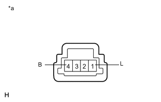
Text in Illustration *a Component without harness connected
(Headlight Cleaner Switch Assembly)
Remove the headlight cleaner switch assembly Click here.
-
Measure the resistance according to the value(s) in the table below.
Standard Resistance Tester Connection Condition Specified Condition 1 (L) - 4 (B) Headlight cleaner switch off 10 kΩ or higher 1 (L) - 4 (B) Headlight cleaner switch on Below 1 Ω
NG
REPLACE HEADLIGHT CLEANER SWITCH ASSEMBLY Click here
OK
-
-
CHECK HARNESS AND CONNECTOR (HEADLIGHT CLEANER SWITCH ASSEMBLY - HEADLIGHT CLEANER CONTROL RELAY)
-
Measure the resistance according to the value(s) in the table below.
Standard Resistance Tester Connection Condition Specified Condition H5-4 (B) - A43-2 (H) Always Below 1 Ω H5-4 (B) - Body ground Always 10 kΩ or higher
NG
REPAIR OR REPLACE HARNESS OR CONNECTOR
OK
-
-
CHECK HARNESS AND CONNECTOR (INSTRUMENT PANEL JUNCTION BLOCK ASSEMBLY - HEADLIGHT CLEANER SWITCH ASSEMBLY)
-
Disconnect the 3A instrument panel junction block assembly.
-
Measure the resistance according to the value(s) in the table below.
Standard Resistance Tester Connection Condition Specified Condition 3A-43 - H5-1 (L) Always Below 1 Ω 3A-43 - Body ground Always 10 kΩ or higher
NG
REPAIR OR REPLACE HARNESS OR CONNECTOR
OK
-
-
INSPECT INSTRUMENT PANEL JUNCTION BLOCK ASSEMBLY
-
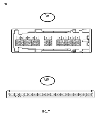
Text in Illustration *a Component without harness connected
(Instrument Panel Junction Block Assembly)
Remove the instrument panel junction block assembly Click here.
-
Measure the resistance according to the value(s) in the table below.
Standard Resistance Tester Connection Condition Specified Condition 3A-43 - MB-15 (HRLY) Always Below 1 Ω 3A-43 - Body ground Always 10 kΩ or higher
OK
REPLACE MAIN BODY ECU (MULTIPLEX NETWORK BODY ECU) Click here
NG
REPLACE INSTRUMENT PANEL JUNCTION BLOCK ASSEMBLY Click here
-