| DTC Code | DTC Name |
|---|---|
| Wiper and Washer Switch Circuit |
DESCRIPTION
This circuit detects the state of the windshield wiper switch assembly (front wiper switch and front washer switch) and sends it to the windshield wiper relay assembly.
CAUTION / NOTICE / HINT
Inspect the fuses for circuits related to this system before performing the following inspection procedure.
PROCEDURE
- Click here
INSPECT WINDSHIELD WIPER SWITCH ASSEMBLY
-
for LHD:
-
Remove the windshield wiper switch assembly (Click here).
-
Measure the resistance according to the value(s) in the table below.
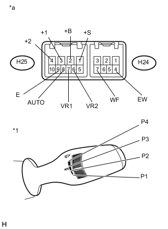
Standard Resistance Table 1. Front Wiper Switch Tester Connection Condition Specified Condition H25-3 (+1) - H25-1 (+S) OFF Below 1 Ω AUTO H25-3 (+1) - H25-2 (+B) MIST LO H25-2 (+B) - H25-4 (+2) HI H25-8 (AUTO) - H25-9 (E) AUTO Table 2. Front Washer Switch Tester Connection Condition Specified Condition H24-4 (EW) - H24-7 (WF) ON Below 1 Ω OFF 10 kΩ or higher Table 3. Adjusting Lever* Tester Connection Condition Specified Condition H25-7 (VR1) - H25-6 (VR2) P1 209 to 231 Ω P2 114 to 126 Ω P3 58.9 to 65.1 Ω P4 Below 1 Ω Tip:*: The rain sensor sensitivity can be adjusted by the windshield wiper switch assembly adjusting lever.
Table 4. Text in Illustration *1 Windshield Wiper Switch Assembly (Adjusting Lever Position) *a Component without harness connected
(Windshield Wiper Switch Assembly)
-
-
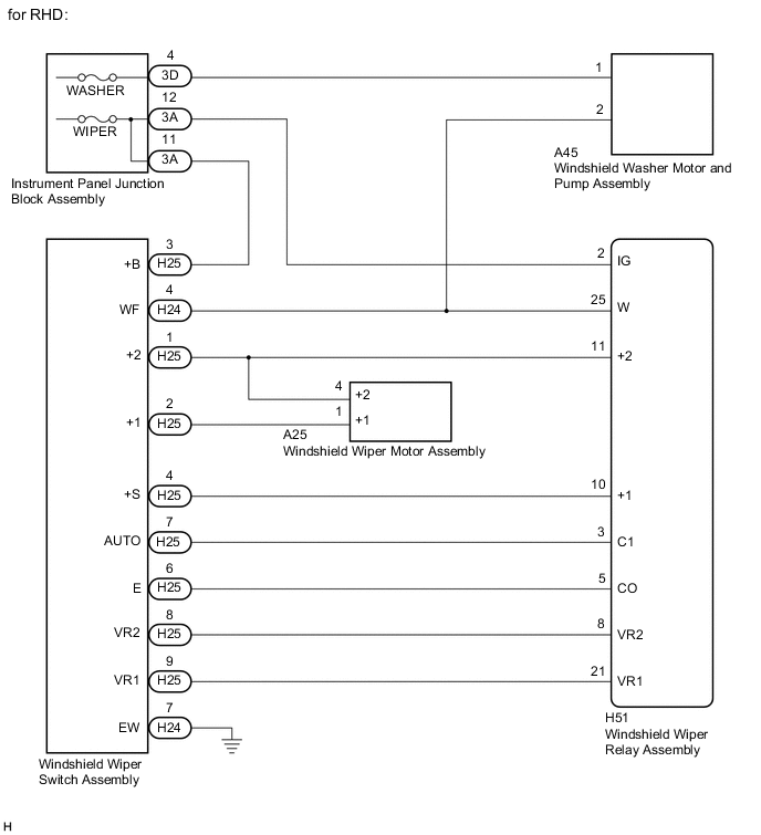
for RHD:
-
Remove the windshield wiper switch assembly (Click here).
-
Measure the resistance according to the value(s) in the table below.
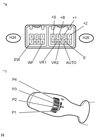
Standard Resistance Table 5. Front Wiper Switch Tester Connection Condition Specified Condition H25-2 (+1) - H25-4 (+S) OFF Below 1 Ω AUTO H25-2 (+1) - H25-3 (+B) MIST LO H25-3 (+B) - H25-1 (+2) HI H25-7 (AUTO) - H25-6 (E) AUTO Table 6. Front Washer Switch Tester Connection Condition Specified Condition H24-7 (EW) - H24-4 (WF) ON Below 1 Ω OFF 10 kΩ or higher Table 7. Adjusting Lever* Tester Connection Condition Specified Condition H25-9 (VR1) - H25-8 (VR2) P1 209 to 231 Ω P2 114 to 126 Ω P3 58.9 to 65.1 Ω P4 Below 1 Ω Tip:*: The rain sensor sensitivity can be adjusted by the windshield wiper switch assembly adjusting lever.
Table 8. Text in Illustration *1 Windshield Wiper Switch Assembly (Adjusting Lever Position) *a Component without harness connected
(Windshield Wiper Switch Assembly)
-
- OKClick here
- NG
REPLACE WINDSHIELD WIPER SWITCH ASSEMBLY (Click here)
-
- Click here
CHECK HARNESS AND CONNECTOR (WINDSHIELD WIPER SWITCH ASSEMBLY - WINDSHIELD WIPER RELAY ASSEMBLY AND BODY GROUND)
-
Disconnect the H51 windshield wiper relay assembly connector.
-
Disconnect the A25 windshield wiper motor assembly.
-
Disconnect the A45 windshield washer motor and pump assembly.
-
Disconnect the 3D instrument panel junction block assembly.
-
Disconnect the 3A instrument panel junction block assembly.
-
Measure the resistance according to the value(s) in the table below.
Standard Resistance Table 9. for LHD Tester Connection Condition Specified Condition H24-4 (EW) - Body ground Always Below 1 Ω H24-7 (WF) - H51-25 (W) Always Below 1 Ω H24-7 (WF) - A45-2 Always Below 1 Ω H24-7 (WF) - Body ground Always 10 kΩ or higher H25-1 (+S) - H51-10 (+1) Always Below 1 Ω H25-1 (+S) - Body ground Always 10 kΩ or higher H25-2 (+B) - 3A-11 Always Below 1 Ω H25-2 (+B) - Body ground Always 10 kΩ or higher H25-3 (+1) - A25-5 (+1) Always Below 1 Ω H25-3 (+1) - Body ground Always 10 kΩ or higher H25-4 (+2) - H51-11 (+2) Always Below 1 Ω H25-4 (+2) - A25-3 (+2) Always Below 1 Ω H25-4 (+2) - Body ground Always 10 kΩ or higher H25-6 (VR2) - H51-8 (VR2) Always Below 1 Ω H25-6 (VR2) - Body ground Always 10 kΩ or higher H25-7 (VR1) - H51-21 (VR1) Always Below 1 Ω H25-7 (VR1) - Body ground Always 10 kΩ or higher H25-8 (AUTO) - H51-3 (C1) Always Below 1 Ω H25-8 (AUTO) - Body ground Always 10 kΩ or higher H25-9 (E) - H51-5 (CO) Always Below 1 Ω H25-9 (E) - Body ground Always 10 kΩ or higher A45-1 - 3D-4 Always Below 1 Ω A45-1 - Body ground Always 10 kΩ or higher Table 10. for RHD Tester Connection Condition Specified Condition H24-7 (EW) - Body ground Always Below 1 Ω H24-4 (WF) - H51-25 (W) Always Below 1 Ω H24-4 (WF) - A45-2 Always Below 1 Ω H24-4 (WF) - Body ground Always 10 kΩ or higher H25-4 (+S) - H51-10 (+1) Always Below 1 Ω H25-4 (+S) - Body ground Always 10 kΩ or higher H25-3 (+B) - 3A-11 Always Below 1 Ω H25-3 (+B) - Body ground Always 10 kΩ or higher H25-2 (+1) - A25-1 (+1) Always Below 1 Ω H25-2 (+1) - Body ground Always 10 kΩ or higher H25-1(+2) - H51-11 (+2) Always Below 1 Ω H25-1 (+2) - A25-4 (+2) Always Below 1 Ω H25-1 (+2) - Body ground Always 10 kΩ or higher H25-8 (VR2) - H51-8 (VR2) Always Below 1 Ω H25-8 (VR2) - Body ground Always 10 kΩ or higher H25-9 (VR1) - H51-21 (VR1) Always Below 1 Ω H25-9 (VR1) - Body ground Always 10 kΩ or higher H25-7 (AUTO) - H51-3 (C1) Always Below 1 Ω H25-7 (AUTO) - Body ground Always 10 kΩ or higher H25-6 (E) - H51-5 (CO) Always Below 1 Ω H25-6 (E) - Body ground Always 10 kΩ or higher A45-1 - 3D-4 Always Below 1 Ω A45-1 - Body ground Always 10 kΩ or higher
- OK
PROCEED TO NEXT SUSPECTED AREA SHOWN IN PROBLEM SYMPTOMS TABLE (Click here)
- NG
REPAIR OR REPLACE HARNESS OR CONNECTOR
-