CAUTION / NOTICE / HINT
-
Use the same procedure for the LH side and RH side.
-
The following procedure is for the LH side.
PROCEDURE
- Click here
PRECAUTION
Note:After turning the power switch off, waiting time may be required before disconnecting the cable from the auxiliary battery negative (-) terminal. Therefore, make sure to read the disconnecting the cable from the auxiliary battery negative (-) terminal notices before proceeding with work (Click here).
- Click here
REMOVE LUGGAGE TRIM SERVICE HOLE COVER
- Click here
DISCONNECT CABLE FROM NEGATIVE AUXILIARY BATTERY TERMINAL
CAUTION:Wait at least 90 seconds after disconnecting the cable from the auxiliary battery negative (-) terminal to disable the SRS system.
Note:When disconnecting the cable, some systems need to be initialized after the cable is reconnected (Click here).
- Click here
REMOVE FRONT DOOR INSIDE HANDLE BEZEL PLUG
- Click here
REMOVE MULTIPLEX NETWORK MASTER SWITCH ASSEMBLY WITH FRONT DOOR ARMREST BASE PANEL (for Driver Side)
- Click here
REMOVE POWER WINDOW REGULATOR SWITCH ASSEMBLY WITH FRONT DOOR ARMREST BASE PANEL (for Front Passenger Side)
- Click here
REMOVE DOOR PULL HANDLE COVER
- Click here
REMOVE COURTESY LIGHT ASSEMBLY
- Click here
REMOVE FRONT DOOR NO. 1 STIFFENER CUSHION
- Click here
REMOVE FRONT DOOR TRIM BOARD SUB-ASSEMBLY
- Click here
REMOVE FRONT DOOR INNER GLASS WEATHERSTRIP
- Click here
REMOVE OUTER MIRROR CONTROL ECU ASSEMBLY (w/ Memory)
- Click here
REMOVE OUTER MIRROR PROTECTOR
-
Remove the outer mirror protector.
-
- Click here
REMOVE OUTER MIRROR INSTALL HOLE COVER
-
w/o Memory:
-
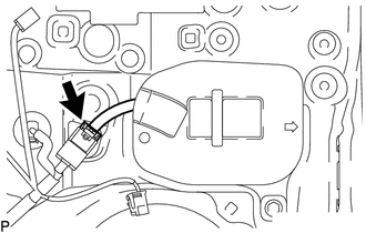
Disconnect the connector.
-
-
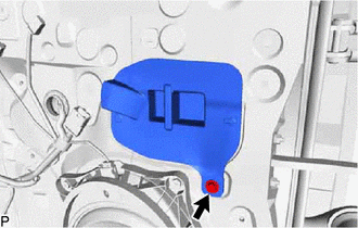
Remove the screw.
-
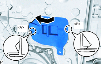
Disengage the claw<A> as shown in the illustration.
-
Disengage the claw<B> and remove the outer mirror install hole cover as shown in the illustration.
-
- Click here
REMOVE OUTER REAR VIEW MIRROR ASSEMBLY
-
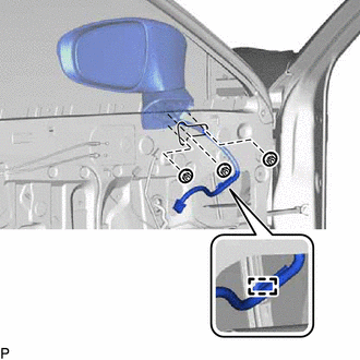
Remove the 3 nuts.
-
Disengage the clamp and remove the outer rear view mirror assembly.
-