POWER MIRROR CONTROL SYSTEM(w/ Memory) OPERATION CHECK
-
CHECK REMOTE CONTROL MIRROR FUNCTION
-
Turn the power switch on (IG).
-
With the mirror select switch set to L, check that the outer mirror LH surface moves up, down, left and right normally.
-
With the mirror select switch set to R, check that the outer mirror RH surface moves up, down, left and right normally.
-
-
CHECK MEMORY AND REACTIVATION FUNCTION
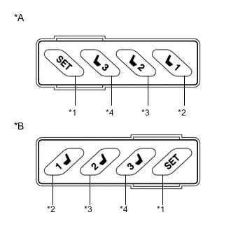
Text in Illustration *A for LHD *B for RHD *1 SET Switch *2 M1 Switch *3 M2 Switch *4 M3 Switch Tech Tips
The SET, M1, M2 and M3 seat memory switches are shown in the illustration.
-
Turn the power switch on (IG) and move the shift lever to P.
-
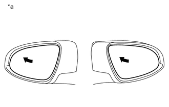
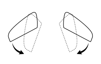
Text in Illustration *a Turn to Fully Left Position Check the M1 switch.
-
Using the mirror adjust switch, turn the mirror surface to the fully left position.
-
Check that the buzzer sounds for 0.5 seconds and the seat and mirror surface position is memorized when the M1 switch is pressed within 3 seconds of the SET switch being pressed.
Note
-
The mirror surface position will also be stored when the M1 switch is pressed after first pressing and holding the SET switch.
-
The mirror surface position will not be stored when the SET switch and M1 switch are pressed simultaneously.
-
The mirror surface position will not be stored when 2 or more of the memory switches are pressed simultaneously (for example, M1 and M2) after first pressing the SET switch.
-
-
Using the outer mirror switch assembly, turn the mirror surface to the fully right position.
-
Press the M1 switch.
-
Check that the buzzer sounds for 0.1 seconds and the outer mirror automatically moves to the recorded fully left position.
-
-
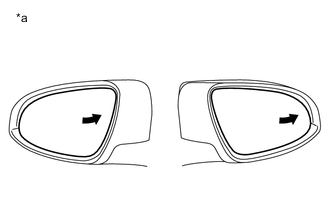
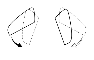
Text in Illustration *a Turn to Fully Right Position Check the M2 switch.
-
Using the mirror adjust switch assembly, turn the mirror surface to the fully right position.
-
Check that the buzzer sounds for 0.5 seconds and the seat and mirror surface position is memorized when the M2 switch is pressed within 3 seconds of the SET switch being pressed.
Note
-
The mirror surface position will also be stored when the M2 switch is pressed after first pressing and holding the SET switch.
-
The mirror surface position will not be stored when the SET switch and M2 switch are pressed simultaneously.
-
The mirror surface position will not be stored when 2 or more of the memory switches are pressed simultaneously (for example, M1 and M2) after first pressing the SET switch.
-
-
Using the outer mirror switch assembly, turn the mirror surface to the fully left position.
-
Press the M2 switch.
-
Check that the buzzer sounds for 0.1 seconds and the outer mirror automatically moves to the recorded fully right position.
-
-
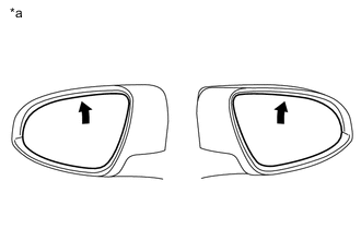
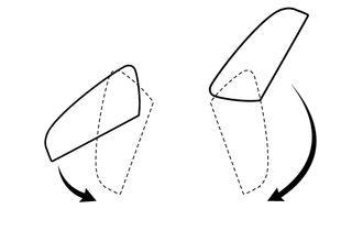
Text in Illustration *a Turn to Fully Upward Position Check the M3 switch.
-
Using the outer mirror switch assembly, turn the mirror surface to the fully upward position.
-
Check that the buzzer sounds for 0.5 seconds and the seat and mirror surface position is memorized when the M3 switch is pressed within 3 seconds after the SET switch is being pressed.
Note
-
The mirror surface position will also be stored when the M3 switch is pressed after first pressing and holding the SET switch.
-
The mirror surface position will not be stored when the SET switch and M3 switch are pressed simultaneously.
-
The mirror surface position will not be stored when 2 or more of the memory switches are pressed simultaneously (for example, M1 and M2) after first pressing the SET switch.
-
-
Using the outer mirror switch assembly, turn the mirror surface to the fully downward position.
-
Press the M3 switch.
-
Check that the buzzer sounds for 0.1 seconds and the outer mirror automatically moves to the recorded fully upward position.
-
-
-
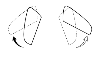
CHECK POWER RETRACTABLE MIRROR FUNCTION
-
Turn the power switch on (IG).
-
At each outer rear view mirror assembly position, check the retractable mirror operation when operating the retractable outer mirror switch.
-
Move both outer rear view mirror assemblies to the driving position.
-
Select driving position on the retractable outer mirror switch.
-
Check that the right and left outer rear view mirror assemblies move from the driving position to the retracted position.
-
Move both outer rear view mirror assemblies to the driving position.
-
Move one of the outer rear view mirror assemblies to the forward position by hand.
-
Select driving position on the retractable outer mirror switch.
-
Check that the outer rear view mirror assembly in the forward position moves to the retracted position, and check that the other mirror moves to the retracted position.
-
Move the outer rear view mirror assemblies to the driving position.
-
Move one of the outer rear view mirror assemblies to the retracted position by hand.
-
Select driving position on the retractable outer mirror switch.
-
Check that the outer rear view mirror assembly in the driving position moves to the retracted position.
-
Move both outer rear view mirror assemblies to the retracted position.
-
Select driving position on the retractable outer mirror switch.
-
Check that both outer rear view mirror assemblies move from the retracted position to the driving position.
-
Move both outer rear view mirror assemblies to the retracted position.
-
Move one of the outer rear view mirror assemblies to the driving position by hand.
-
Select driving position on the retractable outer mirror switch.
-
Check that the retracted outer rear view mirror assembly moves to the driving position.
-
-
Check the operation of the outer rear view mirror assemblies according to retractable outer mirror switch operations and power switch condition.
-
When the outer rear view mirror assemblies are operating, turn the power switch off and check that the mirror operation stops immediately.
-
Turn the power switch on (ACC) and press the retractable outer mirror switch. Check that the outer rear view mirror assemblies operate in the opposite direction.
-
-
Check the operation of the outer rear view mirror assembly when it is blocked by an obstacle.
-
When an outer rear view mirror assembly is moving to the retracted or driving position, block it by hand. Check that stops moving.
-
With the outer rear view mirror assembly stopped partway, push the retractable outer mirror switch. Check that the outer rear view mirror assembly moves in the opposite direction.
-
-
-
CHECK AUTO ELECTRIC RETRACT FUNCTION
Tech Tips
The default setting is Door Lock. If necessary, the function can be set to ACC through the customize function.
-
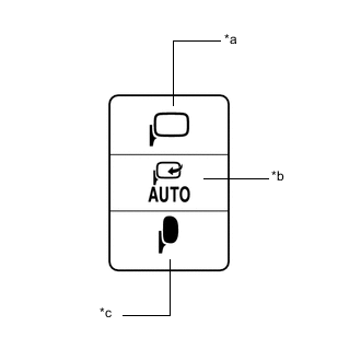
Text in Illustration *a Driving position *b AUTO position *c Retracted position With the power switch off and the retractable outer mirror switch selected, when the doors are unlocked through the entry function, wireless function or key-linked function, check that both outer rear view mirror assemblies move from the retracted position to the driving position, and stop in the driving position.
-
With the power switch off, and the retractable outer mirror switch AUTO position selected, when the doors are locked through the entry function, wireless function or key-linked function, check that both outer rear view mirror assemblies move from the driving position to the retracted position, and stop in the retracted position.
-
When the power switch is on (ACC) and then turned off while the retractable outer mirror switch is in AUTO position, check that both outer rear view mirror assemblies automatically move from the driving position to the retracted position.
-
When the power switch is off and then turned on (ACC) while the retractable outer mirror switch is in the AUTO position, check that both outer rear view mirror assemblies automatically move from the retracted position to the driving position.
-
-
CHECK REVERSE SHIFT-LINKED OPERATION OF MIRRORS
-
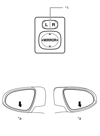
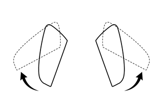
Text in Illustration *1 Mirror Select Switch *a Downward Turn the power switch on (IG).
-
Set the mirror select switch to L or R.
-
Check that the mirror surface turns downward when the shift lever is moved to R.
-
Check that the mirror surface position returns to the original position when one of the following conditions is met:
-
Shift lever is moved to any position other than R.
-
Mirror select switch is in the neutral position (off).
-
power switch is turned off.
-
-
-
CHECK MEMORY CALL FUNCTION
-
Memory call function check
-
With an electrical key transmitter sub-assembly recognition code registered:
Perform a wireless door unlock operation and check that opening the driver side door causes the following:
-
The buzzer sounds for 0.1 seconds.
-
The front seat and mirror surface positions automatically move to the stored positions.
Tech Tips
-
The registered electrical key transmitter sub-assembly recognition code is recalled automatically.
-
If the memory call function is not operated, the buzzer will not sound.
-
-
-
With the power switch on (IG) and the driver door closed, press and hold the M1, M2 or M3 switch while carrying the electrical key transmitter sub-assembly. The main body ECU (multiplex network body ECU) will enter electrical key transmitter sub-assembly recognition code registration mode to allow a key to be linked to mirror surface memory position.
Tech Tips
If the seat memory switch is released before entering registration mode, the main body ECU (multiplex network body ECU) will not enter registration mode.
-
When the manual door lock switch is pressed, check that the buzzer of the position control ECU and switch assembly sounds once (0.5 seconds).
-
With the power switch on (IG) and the driver side door closed, press and hold the SET switch while carrying the electrical key transmitter sub-assembly. The main body ECU (multiplex network body ECU) will enter electrical key transmitter sub-assembly recognition code deletion mode.
Tech Tips
If the SET switch is released before entering deletion mode, the main body ECU (multiplex network body ECU) will not enter deletion mode.
-
When the manual door lock switch is pressed, check that the buzzer of the position control ECU and switch assembly sounds twice (0.1 seconds each time).
-
-
CHECK MEMORY CALL EMERGENCY STOP FUNCTION
-
While a memory call function is operating, check that any one of the following actions will stop the memory call operation: 1) pressing the SET, M1, M2 or M3 switch, 2) moving the shift lever to R, 3) moving the mirror surface manually, or 4) moving the mirror surface to the uppermost, lowermost, leftmost or rightmost position.
-
-
CHECK MIRROR HEATER FUNCTION
-
Turn the power switch on (IG).
-
Check that pressing the mirror heater switch illuminates the indicator and warms the mirror surface.
-
Check that after approximately 15 minutes, the indicator light turns off and the mirror heater deactivates.
Tech Tips
There is a timer extension function which can operate the mirror heater system for up to an additional 45 minutes.
-
-
CHECK AUTOMATIC GLARE-RESISTANT EC MIRROR FUNCTION
-
Check that the automatic glare-resistant EC mirror function of the outer rear view mirror assembly operates when the automatic glare-resistant function of the inner rear view mirror assembly is operating.
-