CAUTION / NOTICE / HINT
| *1 | Centering Bolt |
| *2 | Standard Bolt |
-
Centering bolts are used to mount the door hinge to the door. The door cannot be adjusted with the centering bolts installed. Substitute the centering bolts with standard bolts when making adjustments.
-
Specified torque for standard bolts is shown in the standard bolt chart (Click here).
PROCEDURE
- Click here
REMOVE LUGGAGE COMPARTMENT DOOR ASSIST GRIP
- Click here
REMOVE LUGGAGE COMPARTMENT DOOR COVER
- Click here
REMOVE LUGGAGE COMPARTMENT FLOOR MAT
- Click here
REMOVE SPARE WHEEL COVER PAD LH
- Click here
REMOVE SPARE WHEEL COVER PAD RH
- Click here
REMOVE LUGGAGE HOLD BELT STRIKER ASSEMBLY
- Click here
REMOVE REAR FLOOR FINISH PLATE
- Click here
ADJUST LUGGAGE COMPARTMENT DOOR
-
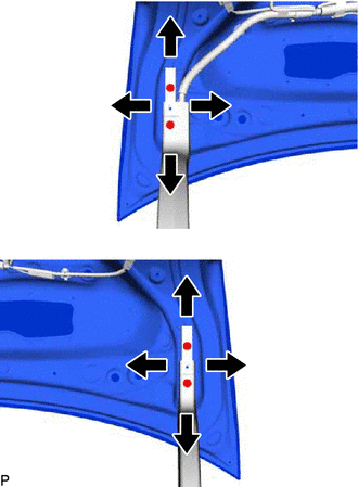
Loosen the 4 door side hinge bolts to adjust the door horizontally and vertically.
7.0 N*m 71 kgf*cm 62 in.*lbf -
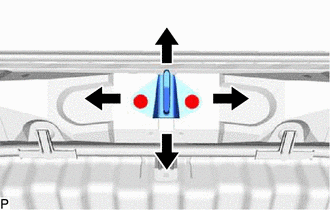
Using a T40 "TORX" socket wrench, slightly loosen the 2 striker mounting screws.
-
Using a brass bar and a hammer, hit the striker to adjust its position.
-
Using a T40 "TORX" socket wrench, tighten the 2 striker mounting screws after adjustment.
23 N*m 235 kgf*cm 17 ft.*lbf
-
- Click here
INSTALL REAR FLOOR FINISH PLATE
- Click here
INSTALL LUGGAGE HOLD BELT STRIKER ASSEMBLY
- Click here
INSTALL SPARE WHEEL COVER PAD RH
- Click here
INSTALL SPARE WHEEL COVER PAD LH
- Click here
INSTALL LUGGAGE COMPARTMENT FLOOR MAT
- Click here
INSTALL LUGGAGE COMPARTMENT DOOR COVER
- Click here
INSTALL LUGGAGE COMPARTMENT DOOR ASSIST GRIP
- Click here
INSPECT LUGGAGE COMPARTMENT DOOR
-

Check that the clearance measurements of areas "a" through "d" are within each standard range.
Table 2. Standard Clearance Area Measurement Area Measurement a 7.0 mm (0.276 in.) b 2.3 to 5.3 mm (0.0906 to 0.209 in.) c -1.5 to 1.5 mm (-0.0591 to 0.0591 in.) d 4.0 to 8.0 mm (0.157 to 0.315 in.)
-