CAUTION / NOTICE / HINT
-
Use the same procedure for the RH side and LH side.
-
The following procedure is for the LH side.
PROCEDURE
- Click here
PRECAUTION
Note:After turning the power switch off, waiting time may be required before disconnecting the cable from the auxiliary battery negative (-) terminal. Therefore, make sure to read the disconnecting the cable from the auxiliary battery negative (-) terminal notices before proceeding with work (Click here).
- Click here
REMOVE LUGGAGE TRIM SERVICE HOLE COVER
- Click here
DISCONNECT CABLE FROM NEGATIVE AUXILIARY BATTERY TERMINAL
Note:When disconnecting the cable, some systems need to be initialized after the cable is reconnected (Click here).
- Click here
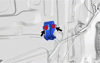
REMOVE FRONT DOOR INSIDE HANDLE BEZEL PLUG
-
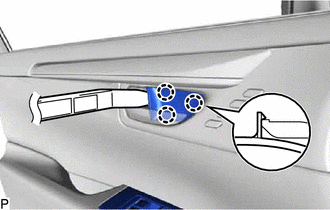
Using a moulding remover, disengage the 3 claws and remove the front door inside handle bezel plug as shown in the illustration.
-
- Click here
REMOVE MULTIPLEX NETWORK MASTER SWITCH ASSEMBLY WITH FRONT DOOR ARMREST BASE PANEL (for Driver Side)
-
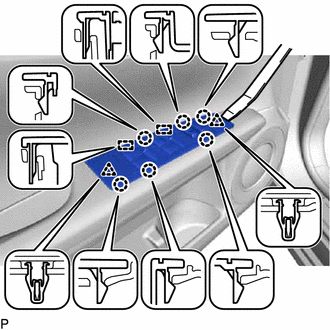
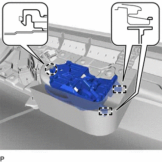
Using a moulding remover, disengage the 2 clips, 6 claws and 2 guides as shown in the illustration.
-
Disconnect each connector and remove the multiplex network master switch assembly with front door armrest base panel.
-
- Click here
REMOVE POWER WINDOW REGULATOR SWITCH ASSEMBLY WITH FRONT DOOR ARMREST BASE PANEL (for Front Passenger Side)
-
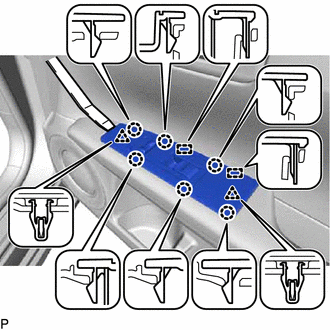
Using a moulding remover, disengage the 2 clips, 6 claws and 2 guides as shown in the illustration.
-
Disconnect each connector and remove the power window regulator switch assembly with front door armrest base panel.
-
- Click here
REMOVE DOOR PULL HANDLE COVER
-
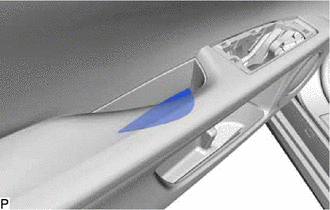
Remove the door pull handle cover.
-
- Click here
REMOVE COURTESY LIGHT ASSEMBLY
- Click here
REMOVE FRONT DOOR NO. 1 STIFFENER CUSHION
-
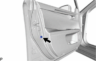
Remove the screw and front door No. 1 stiffener cushion.
-
- Click here
REMOVE FRONT DOOR TRIM BOARD SUB-ASSEMBLY
-
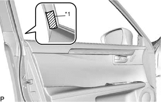
Put protective tape around the front door panel.
Table 1. Text in Illustration *1 Protective Tape -
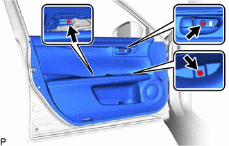
Remove the 3 screws.
-
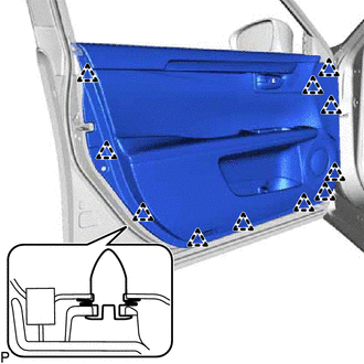
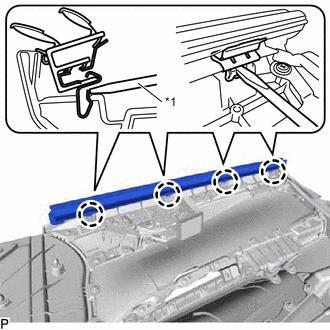
Using a clip remover, disengage the 11 clips.
-
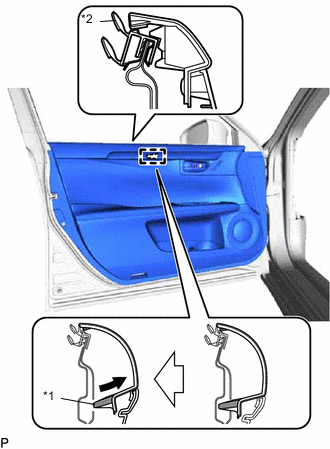
Pull out the front door trim board sub-assembly in the direction indicated by the arrow as shown in the illustration.
Table 2. Text in Illustration *1 Reference Boss *2 Front Door Inner Glass Weatherstrip -
Disengage the reference boss from the front door panel.
-
Raise the front door trim board sub-assembly and disconnect the front door trim board sub-assembly together with the front door inner glass weatherstrip.
-
w/ Memory:
-
Disconnect the connector.
-
-
w/ Illumination:
-
Disconnect the connector.
-
-
Disconnect the front door lock remote control cable assembly and front door inside locking cable assembly to remove the front door trim board sub-assembly together with the front door inner glass weatherstrip.
-
- Click here
REMOVE FRONT DOOR INNER GLASS WEATHERSTRIP
-
Using a screwdriver, disengage the 4 claws and remove the front door inner glass weatherstrip from the front door trim board sub-assembly as shown in the illustration.
Table 3. Text in Illustration *1 Screwdriver
-
- Click here
REMOVE FRONT DOOR INSIDE HANDLE SUB-ASSEMBLY
-
Disengage the claw and 2 guides, and remove the front door inside handle sub-assembly.
-
- Click here
REMOVE SEAT MEMORY SWITCH (w/ Memory)
- Click here
REMOVE FRONT DOOR TRIM ORNAMENT SUB-ASSEMBLY (for Wood Panel)
-
w/ Illumination:
-
Disengage the 3 clamps.
-
-
Remove the 11 screws and front door trim ornament assembly.
-
Remove the screw.
-
Disengage the claw and remove the front door trim ornament sub-assembly.
-
- Click here
REMOVE OUTER MIRROR CONTROL ECU ASSEMBLY (w/ Memory)
- Click here
REMOVE OUTER MIRROR PROTECTOR
- Click here
REMOVE OUTER MIRROR INSTALL HOLE COVER
- Click here
REMOVE OUTER REAR VIEW MIRROR ASSEMBLY
- Click here
REMOVE FRONT DOOR LOWER FRAME BRACKET GARNISH
-
Disengage the 2 clips and remove the front door lower frame bracket garnish.
-
- Click here
REMOVE FRONT NO. 1 SPEAKER ASSEMBLY
- Click here
REMOVE FRONT DOOR ARMREST SET BRACKET
-
Remove the 2 screws and front door armrest set bracket.
-
- Click here
REMOVE FRONT DOOR SERVICE HOLE COVER
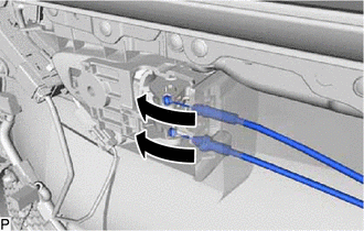
-
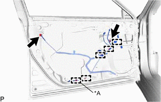
Disconnect the 2 connectors.
Table 4. Text in Illustration *A for LH Side -
Disengage each clamp.
-
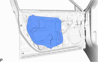
Remove the front door service hole cover.
Tip:Remove any remaining butyl tape from the door.
-
- Click here
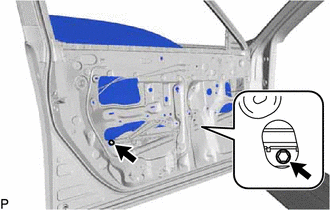
REMOVE FRONT DOOR GLASS SUB-ASSEMBLY
-
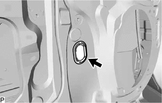
Remove the grommet.
-
Connect the cable to the auxiliary battery negative (-) terminal.
-
Connect the multiplex network master switch assembly and move the front door glass sub-assembly so that the door glass bolts can be seen.
-
Disconnect the cable from the auxiliary battery negative (-) terminal.
-
Disconnect the multiplex network master switch assembly.
-
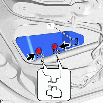
Remove the 2 bolts.
Note:After the bolts are removed, do not allow the front door glass sub-assembly to fall.
-

Remove the front door glass sub-assembly as indicated by the arrows, in the order shown in the illustration.
Note:Do not damage the front door glass sub-assembly.
-
- Click here
REMOVE FRONT DOOR WINDOW REGULATOR ASSEMBLY
-
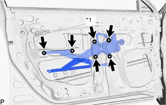
Loosen the temporary bolt.
Table 5. Text in Illustration *1 Temporary Bolt Note:Do not remove the temporary bolt. If the temporary bolt is removed, the front door window regulator assembly may fall and cause damage.
-
Remove the 5 bolts.
-
Remove the front door window regulator assembly.
-
Remove the temporary bolt from the front door window regulator assembly.
-
- Click here
REMOVE FRONT POWER WINDOW REGULATOR MOTOR ASSEMBLY
-
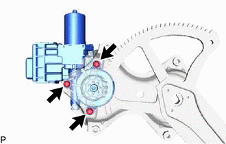
Using a T25 "TORX" socket wrench, remove the 3 screws and front power window regulator motor assembly.
-
- Click here
REMOVE FRONT DOOR GLASS RUN
-
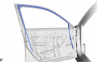
Remove the front door glass run.
-
- Click here
REMOVE FRONT DOOR FRONT LOWER FRAME SUB-ASSEMBLY
-
Remove the 2 bolts.
-
Disengage the guide and remove the front door front lower frame sub-assembly.
-
- Click here
REMOVE FRONT DOOR REAR LOWER FRAME SUB-ASSEMBLY
-
Remove the bolt.
-
Disengage the guide and remove the front door rear lower frame sub-assembly.
-
- Click here
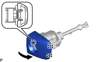
REMOVE FRONT DOOR OUTSIDE HANDLE COVER WITH LOCK CYLINDER ASSEMBLY (for Driver Side)
-
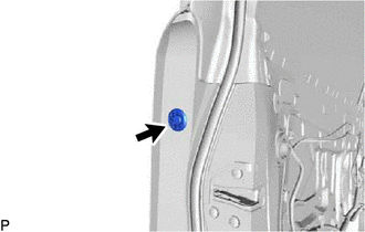
Remove the hole plug.
-
Using a T30 "TORX" socket wrench, loosen the screw and remove the front door outside handle cover with lock cylinder assembly.
Tip:The screw cannot be removed because it is integrated into the front door outside handle frame sub-assembly.
-
- Click here
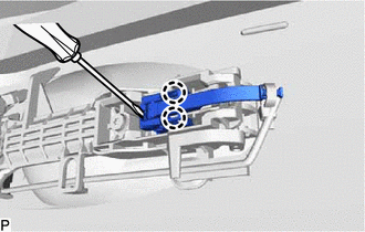
REMOVE FRONT DOOR OUTSIDE HANDLE COVER (for Driver Side)
-
Using a screwdriver, disengage the claw and 2 guides, and remove the front door outside handle cover as shown in the illustration.
-
- Click here
REMOVE FRONT DOOR OUTSIDE HANDLE COVER (for Front Passenger Side)
-
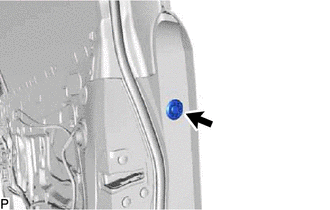
Remove the hole plug.
-
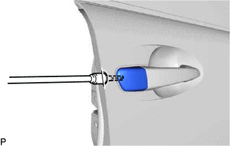
Using a T30 "TORX" socket wrench, loosen the screw and remove the front door outside handle cover.
Tip:The screw cannot be removed because it is integrated into the front door outside handle frame sub-assembly.
-
- Click here
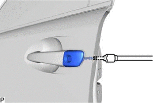
REMOVE FRONT DOOR OUTSIDE HANDLE ASSEMBLY
-
Disengage the 2 claws.
-
Using a screwdriver, disconnect the connector.
-
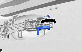
Move the lever in the direction indicated by the arrow in the illustration.
-
Remove the front door outside handle assembly as shown in the illustration.
-
- Click here
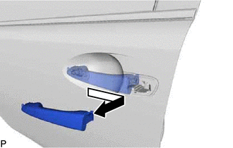
REMOVE FRONT DOOR FRONT OUTSIDE HANDLE PAD
-
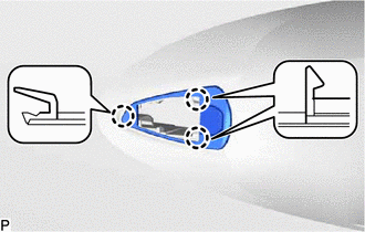
Disengage the 3 claws and remove the front door front outside handle pad.
-
- Click here
REMOVE FRONT DOOR REAR OUTSIDE HANDLE PAD
-
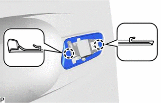
Disengage the 2 claws and remove the front door rear outside handle pad.
-
- Click here
REMOVE FRONT DOOR LOCK ASSEMBLY
-
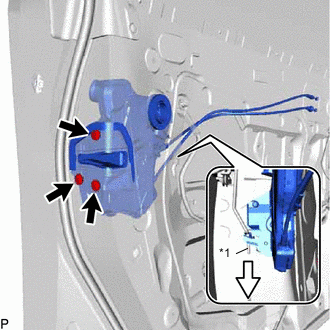
Using a T30 "TORX" socket wrench, remove the 3 screws.
Table 6. Text in Illustration *1 Front Door Lock Open Rod -
Slide the front door lock assembly downward, and remove the front door lock assembly and cables as a unit.
-
When reusing the front door lock assembly:
-
Remove the door lock wiring harness seal from the front door lock assembly.
-
-
- Click here
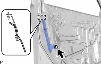
REMOVE FRONT DOOR LOCK REMOTE CONTROL CABLE ASSEMBLY
-
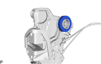
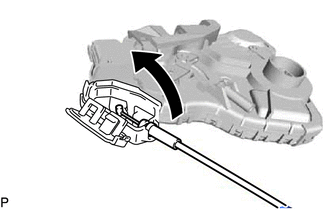
Remove the front door lock remote control cable assembly as shown in the illustration.
-
- Click here
REMOVE FRONT DOOR INSIDE LOCKING CABLE ASSEMBLY
-
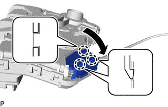
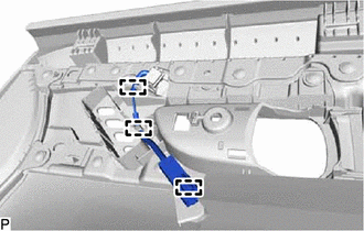
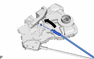
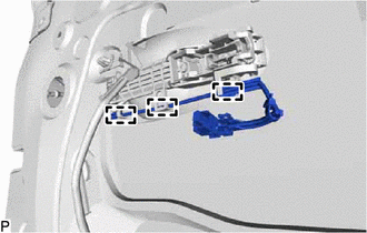
Using a screwdriver, disengage the 3 claws as shown in the illustration.
-
Remove the front door inside locking cable assembly as shown in the illustration.
-
- Click here
REMOVE FRONT DOOR OUTSIDE HANDLE FRAME SUB-ASSEMBLY
-
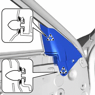
Disengage the 3 clamps.
-
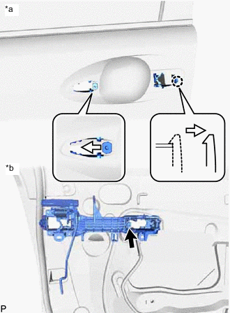
Using a T30 "TORX" socket wrench, loosen the screw.
Table 7. Text in Illustration *a Outside *b Inside -
Slide the front door outside handle frame sub-assembly to disengage the claw of the front door outside handle frame sub-assembly, and then remove it.
-
- Click here
REMOVE FRONT DOOR LOCK OPEN ROD
-
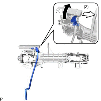
Remove the front door lock open rod as indicated by the arrows and in the order shown in the illustration.
-
- Click here
REMOVE FRONT DOOR NO. 2 STIFFENER CUSHION
-
Remove the 2 bolts.
Table 8. Text in Illustration *1 Double-sided Tape -
Disengage the 2 guides and remove the front door No. 2 stiffener cushion.
-
- Click here
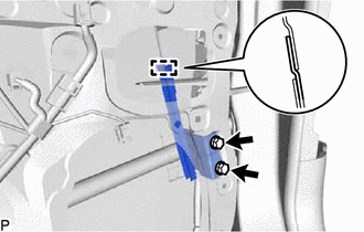
REMOVE FRONT DOOR CHECK ASSEMBLY
-
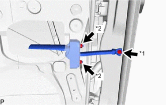
Remove the bolt and 2 nuts, and front door check assembly.
Table 9. Text in Illustration *1 Bolt *2 Nut
-
- Click here
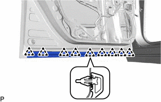
REMOVE FRONT DOOR WEATHERSTRIP
-
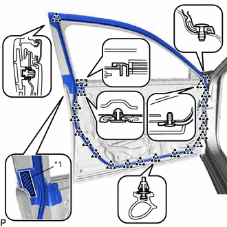
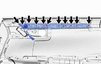
Using a clip remover, disengage the 21 clips and guide, and remove the front door weatherstrip.
Table 10. Text in Illustration *1 Double-sided Tape
-
- Click here
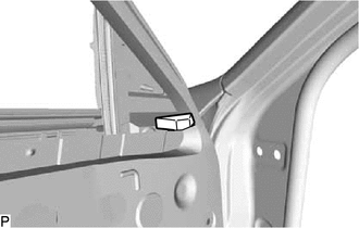
REMOVE DOOR FRAME GARNISH
-
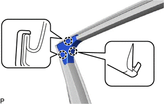
Disengage the 3 claws and remove the door frame garnish.
-
- Click here
REMOVE FRONT DOOR NO. 2 WEATHERSTRIP
-
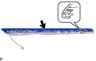
Using a clip remover, disengage the 9 clips and remove the front door No. 2 weatherstrip.
-
- Click here
REMOVE FRONT DOOR PANEL CUSHION
-
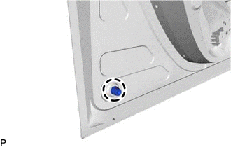
Disengage the claw and remove the front door panel cushion.
-
- Click here
REMOVE FRONT DOOR LOWER FRAME GARNISH PAD
-
Remove the front door lower frame garnish pad.
-
- Click here
REMOVE FRONT DOOR FRONT LOWER FRAME UPPER COVER
- Click here
REMOVE FRONT DOOR BELT MOULDING ASSEMBLY
- Click here
REMOVE FRONT DOOR REAR WINDOW FRAME MOULDING
- Click here
REMOVE FRONT DOOR OUTSIDE MOULDING SUB-ASSEMBLY
- Click here
REMOVE FRONT DOOR REAR INNER BLACK OUT TAPE
- Click here
REMOVE FRONT INNER BLACK OUT TAPE