PROCEDURE
- Click here
INSTALL SLIDING ROOF HOUSING SUB-ASSEMBLY
-
Install the sliding roof housing sub-assembly with the 8 bolts and 8 nuts.
Nut 5.5 N*m 56 kgf*cm 49 in.*lbf Bolt 8.0 N*m 82 kgf*cm 71 in.*lbf -
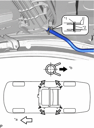
Expand the clip to insert the sliding roof drain hose.
Table 1. Text in Illustration *1 Marking *2 Clip *a Front Side *b Outside Tip:The hose should be inserted to the base of the drain pipe.
-
Release the clip to connect the sliding roof drain hose.
Note:The clip must face toward the outside of the vehicle and also be above the lower surface of the sliding roof housing when installing the drain hoses.
Tip:
-
Make sure that the clip is on the marking or between the marking and hose end.
-
Use the same procedure for the other 3 sliding roof drain hoses.
-
-
- Click here
INSTALL CURTAIN SHIELD AIRBAG ASSEMBLY LH
- Click here
INSTALL CURTAIN SHIELD AIRBAG ASSEMBLY RH
Tip:Use the same procedure as for the LH side.
- Click here
INSTALL SLIDING ROOF WEATHERSTRIP
-
Install the sliding roof weatherstrip as follows:
-
Position the joint of the weatherstrip at the rear center.
-
Align the alignment mark (green) on the weatherstrip with the middle marks at the corners of the sliding roof panel sub-assembly and install the weatherstrip.
-
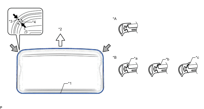
Install the lip of the weatherstrip firmly.
Table 2. Text in Illustration *A Correct *B Incorrect *1 Joint *2 Front *3 Alignment Mark (Green) *4 Middle Mark *a Pinched *b Exposed *c Gap (raised, wavy, etc.) - -
-
-
- Click here
INSTALL SLIDING ROOF GLASS SUB-ASSEMBLY
-
Using a T25 "TORX" socket wrench, temporarily install the sliding roof glass sub-assembly with the 4 screws.
-
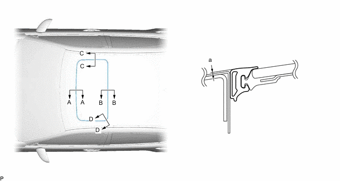
Perform a level check.
-
Check the difference in level for "a" between the roof panel and the upper surface of the weatherstrip when the sliding roof glass is fully closed.
Standard Area Measurement A - A 0 + 1.0 mm (0 + 0.0394 in.)
0 - 2.0 mm (0 - 0.0787 in.)
B - B 0 + 2.0 mm (0 + 0.0787 in.)
0 - 1.0 mm (0 - 0.0394 in.)
C - C 0 + 1.5 mm (0 + 0.0591 in.)
0 - 1.5 mm (0 - 0.0591 in.)
D - D 0 + 1.5 mm (0 + 0.0591 in.)
0 - 1.0 mm (0 - 0.0394 in.)
Tip:"+" represents the condition that the glass is above the panel level. "-" represents the condition that the glass is below the panel level.
-
-
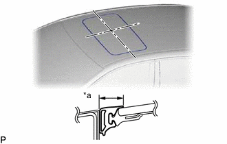
Perform a gap check.
-
Check the gap between the roof panel and roof glass.
Table 3. Text in Illustration *a Even Note:The gap must be even all around.
-
-
After adjusting the sliding roof glass, using a T25 "TORX" socket wrench, install the sliding roof glass sub-assembly with the 4 screws.
5.5 N*m 56 kgf*cm 49 in.*lbf
-
- Click here
CHECK FOR WATER LEAK
-
After adjusting the sliding roof glass sub-assembly, check for water leakage into the vehicle interior.
-
If there are any leaks, readjust the sliding roof glass sub-assembly.
-
- Click here
INSTALL SLIDING ROOF SIDE GARNISH LH
-
Engage the 2 claws to install a new sliding roof side garnish LH.
-
- Click here
INSTALL SLIDING ROOF SIDE GARNISH RH
Tip:Use the same procedure as for the LH side.
- Click here
INSTALL ROOF HEADLINING ASSEMBLY
- Click here
RESET SLIDING ROOF DRIVE GEAR SUB-ASSEMBLY
- Click here
CHECK SLIDING ROOF SYSTEM