PROCEDURE
- Click here
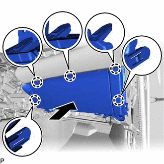
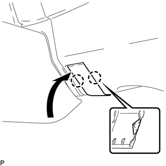
INSTALL INSTRUMENT PANEL SAFETY PAD ASSEMBLY
-
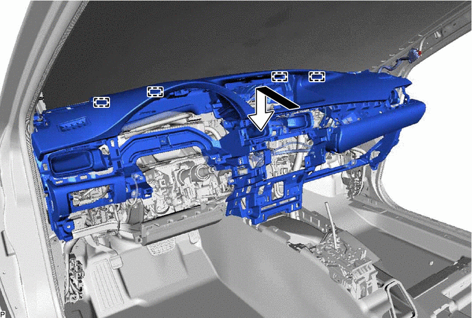
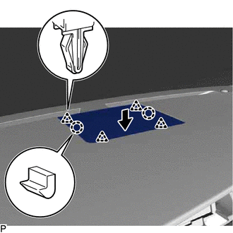
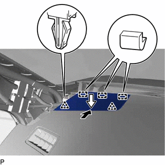
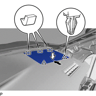
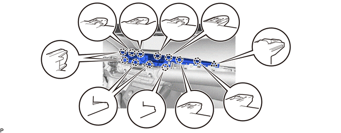
Engage the 4 guides and temporarily install the instrument panel safety pad assembly as shown in the illustration.
Note:
-
Do not damage the instrument panel safety pad assembly.
-
Do not allow the wire harnesses to interfere with the surrounding parts.
-
-
Install the 3 clips.
-
Install the 4 bolts <C> and nut <F>.
-
Install the 2 bolts <A>.
20 N*m 204 kgf*cm 15 ft.*lbf -
Engage the 2 claws to connect the cooler (room temp. sensor) thermistor.
-
Engage each clamp.
-
Connect each connector.
-
- Click here
CONNECT NO. 2 INSTRUMENT PANEL WIRE
- Click here
INSTALL INSTRUMENT PANEL FINISH PANEL SUB-ASSEMBLY
-
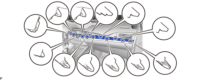
Engage the 8 claws to install the instrument panel finish panel sub-assembly.
-
- Click here
INSTALL NO. 1 ION GENERATOR SUB-ASSEMBLY (w/ Ion Generator)
- Click here
INSTALL FRONT NO. 3 SPEAKER ASSEMBLY
- Click here
INSTALL NO. 1 SPEAKER OPENING COVER ASSEMBLY
-
Engage the 2 claws and 4 clips to install the No. 1 speaker opening cover assembly.
-
- Click here
INSTALL FRONT NO. 2 SPEAKER ASSEMBLY (for LH Side)
- Click here
INSTALL NO. 1 INSTRUMENT PANEL SPEAKER PANEL SUB-ASSEMBLY
-
Engage the 3 guides.
-
Engage the 2 clips to install the No. 1 instrument panel speaker panel sub-assembly.
-
- Click here
INSTALL FRONT PILLAR GARNISH LH
- Click here
INSTALL FRONT NO. 2 SPEAKER ASSEMBLY (for RH Side)
Tip:Use the same procedure as for the LH side (Click here).
- Click here
INSTALL NO. 2 INSTRUMENT PANEL SPEAKER PANEL SUB-ASSEMBLY
-
Engage the 3 guides.
-
Engage the 2 clips to install the No. 2 instrument panel speaker panel sub-assembly.
-
- Click here
INSTALL FRONT PILLAR GARNISH RH
Tip:Use the same procedure as for the LH side (Click here).
- Click here
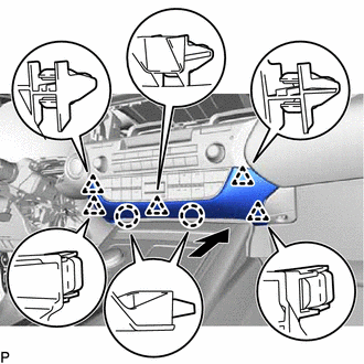
INSTALL NO. 3 INSTRUMENT PANEL REGISTER ASSEMBLY
-
Engage the 4 claws, 2 clips and 2 guides to install the No. 3 instrument panel register assembly.
-
- Click here
INSTALL LOWER INSTRUMENT PANEL SUB-ASSEMBLY
-
Connect each connector.
-
Engage the 5 claws.
-
Install the 2 screws <E>.
-
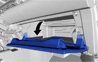
Open the lower instrument panel sub-assembly door as shown in the illustration.
-
Install the lower instrument panel sub-assembly with the 3 screws <E>.
-
- Click here
INSTALL INSTRUMENT PANEL BOX DOOR COVER
-
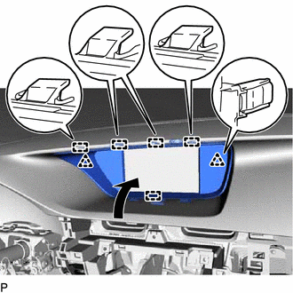
Engage the 4 claws to install the instrument panel box door cover as shown in the illustration.
-
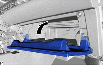
Close the lower instrument panel sub-assembly door as shown in the illustration.
-
- Click here
INSTALL LOWER NO. 2 INSTRUMENT PANEL AIRBAG ASSEMBLY
- Click here
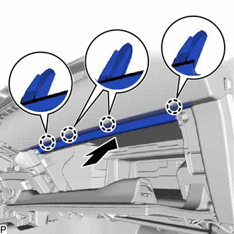
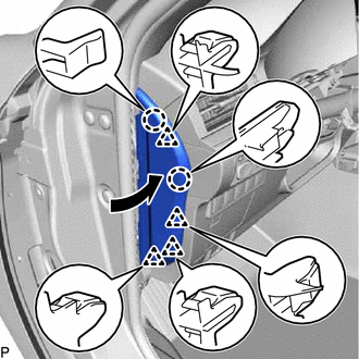
INSTALL NO. 2 INSTRUMENT PANEL UNDER COVER SUB-ASSEMBLY
-
Connect the connector.
-
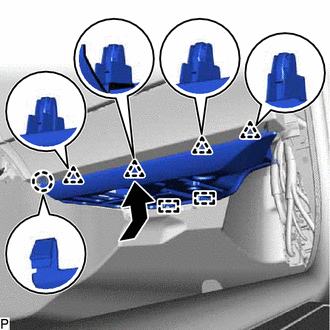
Engage the 2 guides, claw and 4 clips to install the No. 2 instrument panel under cover sub-assembly as shown in the illustration.
-
- Click here
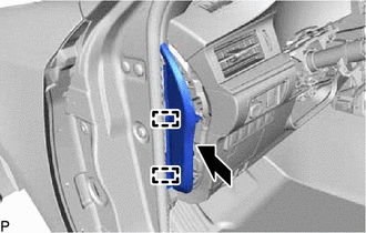
INSTALL INSTRUMENT SIDE PANEL RH
-
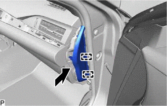
Engage the 2 guides as shown in the illustration.
-
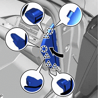
Engage the 2 claws and 4 clips to install the instrument side panel RH as shown in the illustration.
-
- Click here
INSTALL FRONT DOOR OPENING TRIM COVER RH
Tip:Use the same procedure as for the LH side (Click here).
- Click here
INSTALL COWL SIDE TRIM BOARD RH
Tip:Use the same procedure as for the LH side (Click here).
- Click here
INSTALL FRONT DOOR SCUFF PLATE RH
Tip:Use the same procedure as for the LH side (Click here).
- Click here
INSTALL REAR CONSOLE BOX ASSEMBLY
- Click here
INSTALL ACCESSORY METER ASSEMBLY (w/o Navigation System)
- Click here
INSTALL MULTI-DISPLAY ASSEMBLY (w/ Navigation System)
- Click here
INSTALL CENTER INSTRUMENT CLUSTER FINISH PANEL SUB-ASSEMBLY
-
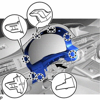
Engage the 2 clips and 5 guides as shown in the illustration.
-
Install the center instrument cluster finish panel sub-assembly with the 2 clips.
-
- Click here
INSTALL SWITCH BASE
-
for LHD:
-
Connect the connector.
-
Engage the 3 claws to install the switch base.
-
-
for RHD:
-
Connect the connector.
-
Engage the 4 claws to install the switch base.
-
-
- Click here
INSTALL NO. 1 INSTRUMENT PANEL REGISTER ASSEMBLY
-
Engage the 6 claws and 2 guides to install the No. 1 instrument panel register assembly.
-
- Click here
INSTALL NO. 1 SWITCH HOLE BASE
-
Connect each connector.
-
Engage the 4 claws to install the No. 1 switch hole base.
-
- Click here
INSTALL COMBINATION METER ASSEMBLY
- Click here
INSTALL LOWER NO. 1 INSTRUMENT PANEL FINISH PANEL
-
for LHD:
-
Connect each connector.
-
Engage the 12 claws, 2 clips and guide.
-
Install the lower No. 1 instrument panel finish panel with the 2 bolts <B>.
-
-
for RHD:
-
Connect each connector and engage each clamp.
-
Engage the 6 claws, 3 clips and guide.
-
Install the lower No. 1 instrument panel finish panel with the 2 bolts <B>.
-
Engage the 2 claws to close the cover as shown in the illustration.
-
-
- Click here
CONNECT HOOD LOCK CONTROL LEVER SUB-ASSEMBLY
-
Engage the claw and 2 guides to connect the hood lock control lever sub-assembly.
-
- Click here
INSTALL INSTRUMENT SIDE PANEL LH
-
Engage the 2 guides.
-
Engage the 2 claws and 4 clips to install the instrument side panel LH as shown in the illustration.
-
- Click here
INSTALL FRONT DOOR OPENING TRIM COVER LH
- Click here
INSTALL COWL SIDE TRIM BOARD LH
- Click here
INSTALL FRONT DOOR SCUFF PLATE LH
- Click here
INSTALL RADIO RECEIVER ASSEMBLY WITH BRACKET (w/o Navigation System)
- Click here
INSTALL MULTI-MEDIA MODULE RECEIVER ASSEMBLY WITH BRACKET (w/ Navigation System)
- Click here
INSTALL LOWER CENTER INSTRUMENT PANEL FINISH PANEL
-
Engage the 2 claws and 5 clips to install the lower center instrument panel finish panel as shown in the illustration.
-
- Click here
INSTALL NO. 2 INSTRUMENT PANEL REGISTER ASSEMBLY
-
Connect the connector.
-
Engage the 11 claws and clip to install the No. 2 instrument panel register assembly.
Note:When installing the No. 2 instrument panel register assembly, check that the wire harness is not caught between the No. 2 instrument panel register assembly and duct.
-
- Click here
INSTALL CENTER INSTRUMENT CLUSTER FINISH PANEL GARNISH
-
Connect the connector.
-
Engage the 10 claws and 2 clips to install the center instrument cluster finish panel garnish.
-
- Click here
INSTALL INSTRUMENT CLUSTER FINISH PANEL SUB-ASSEMBLY
-
Connect the connector.
-
Engage the 5 claws and 2 guides as shown in the illustration.
-
Install the instrument cluster finish panel subassembly with the 2 screws <E>.
-
- Click here
INSTALL TURN SIGNAL SWITCH ASSEMBLY WITH SPIRAL CABLE SUB-ASSEMBLY
- Click here
INSTALL UPPER STEERING COLUMN COVER
- Click here
INSTALL LOWER STEERING COLUMN COVER (for Manual Tilt and Manual Telescopic Steering Column)
- Click here
INSTALL LOWER STEERING COLUMN COVER (for Power Tilt and Power Telescopic Steering Column)
- Click here
INSTALL STEERING WHEEL ASSEMBLY
- Click here
INSTALL HORN BUTTON ASSEMBLY
- Click here
CONNECT CABLE TO NEGATIVE AUXILIARY BATTERY TERMINAL
Note:When disconnecting the cable, some systems need to be initialized after the cable is reconnected (Click here).
-
for Power Tilt and Power Telescopic Steering Column:
-
Reset the auto away/return function setting to the previous condition by changing the customize parameter (Click here).
-
-
- Click here
INSTALL LUGGAGE TRIM SERVICE HOLE COVER
- Click here
INSPECT SRS WARNING LIGHT