REAR SUNSHADE SYSTEM Rear Sunshade does not Operate with Rear Sunshade Switch
DESCRIPTION
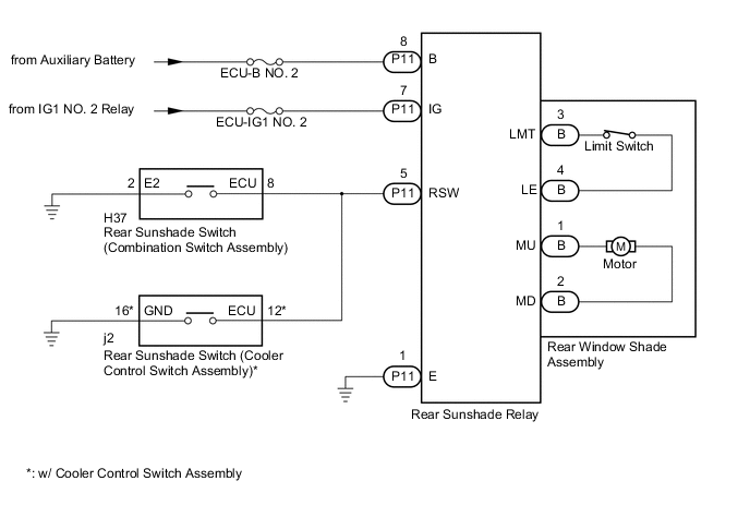
When the rear sunshade switch is pushed, an operation signal is sent to the rear sunshade relay.
WIRING DIAGRAM
CAUTION / NOTICE / HINT
Note
Inspect the fuses for circuits related to this system before performing the following inspection procedure.
PROCEDURE
-
SYSTEM CHECK
-
Check the vehicle specification.
Result Result Proceed to w/ Cooler Control Switch Assembly A w/o Cooler Control Switch Assembly B
B 
INSPECT REAR SUNSHADE SWITCH (COMBINATION SWITCH ASSEMBLY) Click here
A 
-
-
CHECK REAR SUNSHADE OPERATION
-
Check rear sunshade operation Click here.
Result Result Proceed to The rear sunshade does not operate with rear sunshade switch (combination switch assembly) operation. A The rear sunshade does not operate with rear sunshade switch (cooler control switch assembly) operation. B The rear sunshade does not operate with rear sunshade switch (combination switch assembly) and rear sunshade switch (cooler control switch assembly) operation. C
B
INSPECT REAR SUNSHADE SWITCH (COOLER CONTROL SWITCH ASSEMBLY) Click here
C
CHECK HARNESS AND CONNECTOR (AUXILIARY BATTERY - REAR SUNSHADE RELAY - BODY GROUND) Click here
A
-
-
INSPECT REAR SUNSHADE SWITCH (COMBINATION SWITCH ASSEMBLY)
-
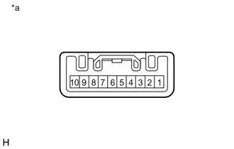
Text in Illustration *a Component without harness connected
(Rear Sunshade Switch (Combination Switch Assembly))
Remove the rear sunshade switch (combination switch assembly) Click here.
-
Measure the resistance according to the value(s) in the table below.
Standard Resistance Tester Connection Condition Specified Condition 2 - 8 Rear sunshade switch pushed Below 1 Ω 2 - 8 Rear sunshade switch not pushed 10 kΩ or higher
NG 
REPLACE REAR SUNSHADE SWITCH (COMBINATION SWITCH ASSEMBLY) Click here
OK
-
-
CHECK HARNESS AND CONNECTOR (REAR SUNSHADE RELAY - REAR SUNSHADE SWITCH (COMBINATION SWITCH ASSEMBLY) - BODY GROUND)
-
Disconnect the P11 rear sunshade relay connector.
-
Measure the resistance according to the value(s) in the table below.
Standard Resistance Tester Connection Condition Specified Condition P11-5 (RSW) - H37-8 (ECU) Always Below 1 Ω P11-5 (RSW) - Body ground Always 10 kΩ or higher H37-2 (E2) - Body ground Always Below 1 Ω Result Result Proceed to OK (w/ Cooler Control Switch Assembly) A OK (w/o Cooler Control Switch Assembly) B NG C
A
REPLACE REAR SUNSHADE RELAY Click here
B
CHECK HARNESS AND CONNECTOR (AUXILIARY BATTERY - REAR SUNSHADE RELAY - BODY GROUND) Click here
C
REPAIR OR REPLACE HARNESS OR CONNECTOR
-
-
INSPECT REAR SUNSHADE SWITCH (COOLER CONTROL SWITCH ASSEMBLY)
-
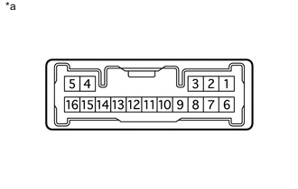
Text in Illustration *a Component without harness connected
(Rear Sunshade Switch (Cooler Control Switch Assembly))
Remove the rear sunshade switch (cooler control switch assembly) Click here.
-
Measure the resistance according to the value(s) in the table below.
Standard Resistance Tester Connection Condition Specified Condition 12 - 16 Rear sunshade switch pushed Below 1 Ω 12 - 16 Rear sunshade switch not pushed 10 kΩ or higher
NG
REPLACE REAR SUNSHADE SWITCH (COOLER CONTROL SWITCH ASSEMBLY) Click here
OK
-
-
CHECK HARNESS AND CONNECTOR (REAR SUNSHADE RELAY - REAR SUNSHADE SWITCH (COOLER CONTROL SWITCH ASSEMBLY) - BODY GROUND)
-
Disconnect the P11 rear sunshade relay connector.
-
Measure the resistance according to the value(s) in the table below.
Standard Resistance Tester Connection Condition Specified Condition P11-5 (RSW) - j2-12 (ECU) Always Below 1 Ω P11-5 (RSW) - Body ground Always 10 kΩ or higher j2-16 (GND) - Body ground Always Below 1 Ω
OK
REPLACE REAR SUNSHADE RELAY Click here
NG
REPAIR OR REPLACE HARNESS OR CONNECTOR
-
-
CHECK HARNESS AND CONNECTOR (AUXILIARY BATTERY - REAR SUNSHADE RELAY - BODY GROUND)
-
Disconnect the P11 rear sunshade relay connector.
-
Measure the voltage and resistance according to the value(s) in the table below.
Standard Voltage Tester Connection Condition Specified Condition P11-8 (B) - Body ground Power switch off 11 to 14 V P11-7 (IG) - Body ground Power switch off Below 1 V P11-7 (IG) - Body ground Power switch on (IG) 11 to 14 V Standard Resistance Tester Connection Condition Specified Condition P11-1 (E) - Body ground Always Below 1 Ω
NG
REPAIR OR REPLACE HARNESS OR CONNECTOR
OK
-
-
INSPECT REAR WINDOW SHADE ASSEMBLY (MOTOR)
-
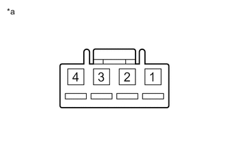
Text in Illustration *a Component without harness connected
(Rear Window Shade Assembly)
Remove the rear window shade assembly Click here.
-
Remove the rear sunshade relay cover from the rear window shade assembly.
-
Disconnect the B rear window shade assembly connector.
-
Apply auxiliary battery voltage and check the operation of the rear sunshade assembly.
OK Connection Result Auxiliary battery positive (+) → 1
Auxiliary battery negative (-) → 2
Rear sunshade raises Auxiliary battery positive (+) → 2
Auxiliary battery negative (-) → 1
Rear sunshade lowers
NG
REPLACE REAR WINDOW SHADE ASSEMBLY
OK
-
-
INSPECT REAR WINDOW SHADE ASSEMBLY (LIMIT SWITCH)
-
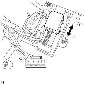
Text in Illustration *1 On *2 Off *a Component without harness connected
(Rear Window Shade Assembly)
Measure the resistance according to the value(s) in the table below.
Standard Resistance Tester Connection Condition Specified Condition 3 - 4 Limit switch on Below 1 Ω 3 - 4 Limit switch off 10 kΩ or higher
OK
REPLACE REAR SUNSHADE RELAY Click here
NG
REPLACE REAR WINDOW SHADE ASSEMBLY
-