PROCEDURE
- Click here
PRECAUTION
CAUTION:Be sure to read Precaution thoroughly before servicing (Click here).
Note:After turning the power switch off, waiting time may be required before disconnecting the cable from the negative (-) auxiliary battery terminal. Therefore, make sure to read the disconnecting the cable from the negative (-) auxiliary battery terminal notices before proceeding with work (Click here).
- Click here
REMOVE LUGGAGE TRIM SERVICE HOLE COVER
- Click here
DISCONNECT CABLE FROM NEGATIVE AUXILIARY BATTERY TERMINAL
- Click here
REMOVE LOWER NO. 3 STEERING WHEEL COVER
- Click here
REMOVE LOWER NO. 2 STEERING WHEEL COVER
- Click here
REMOVE HORN BUTTON ASSEMBLY
- Click here
REMOVE STEERING WHEEL ASSEMBLY
- Click here
ALIGN FRONT WHEELS FACING STRAIGHT AHEAD
- Click here
REMOVE LOWER STEERING COLUMN COVER
- Click here
REMOVE UPPER STEERING COLUMN COVER
- Click here
REMOVE SPIRAL CABLE WITH SENSOR SUB-ASSEMBLY
Note:
-
Do not replace the spiral cable with sensor sub-assembly with the auxiliary battery connected and the power switch on (IG).
-
Do not rotate the spiral cable with sensor sub-assembly without the steering wheel with the auxiliary battery connected and the power switch on (IG).
-
Ensure that the steering wheel is installed and aligned straight when inspecting the steering sensor.
-
Check that the power switch is off.
-
Check that the cable is disconnected from the negative (-) auxiliary battery terminal.
CAUTION:Wait at least 90 seconds after disconnecting the cable from the negative (-) auxiliary battery terminal to disable the SRS system.
-
Check that the front wheels are facing straight ahead.
-
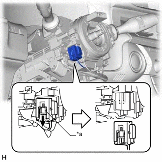
Slide the slider to release the lock, and then disconnect the yellow airbag connector from the spiral cable with sensor sub-assembly.
Table 1. Text in Illustration *a Slider Note:When disconnecting any airbag connector, take care not to damage the airbag wire harness.
-
Disconnect the other connector from the spiral cable with sensor sub-assembly.
-
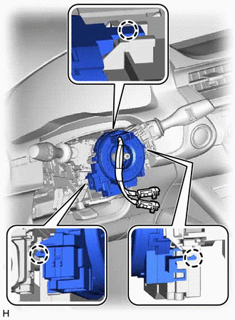
Disengage the 3 claws to remove the spiral cable with sensor sub-assembly.
-
- Click here
REMOVE SPIRAL CABLE SUB-ASSEMBLY
Note:
-
Remove the steering sensor from the spiral cable sub-assembly only when replacing the spiral cable sub-assembly or the steering sensor.
-
Removing the steering sensor from the spiral cable sub-assembly without using a lock pin may result in the center position of the steering sensor becoming misaligned. Therefore, make sure to use the lock pin provided with a new spiral cable sub-assembly when removing the steering sensor from the spiral cable sub-assembly.
-
When replacing the steering sensor: (Click here)
-
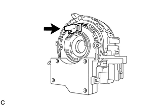
Install the lock pin to the steering sensor.
Note:
-
Use the lock pin provided with a new spiral cable sub-assembly.
-
Do not remove the lock pin before installing the steering sensor to the spiral cable sub-assembly.
-
-
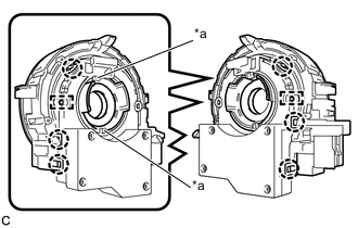
Disengage the 6 claws and 2 pins, and remove the spiral cable sub-assembly from the steering sensor.
Table 2. Text in Illustration *a Guide Note:Do not damage the pins of the spiral cable sub-assembly and guides of the steering sensor.
-