TRIP SWITCH INSPECTION
PROCEDURE
-
INSPECT TRIP SWITCH
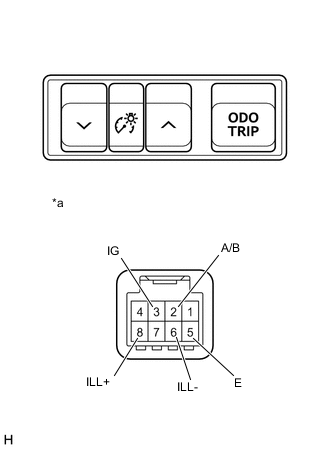
Text in Illustration *a Component without harness connected
(Trip Switch)
-
Measure the resistance according to the value(s) in the table below.
Standard Resistance Tester Connection Condition Specified Condition 2 (A/B) - 5 (E) ODO/TRIP switch not pressed 10 kΩ or higher ODO/TRIP switch pressed Below 1 Ω 3 (IG) - 5 (E) Light control rheostat up switch not pressed 10 kΩ or higher Light control rheostat up switch pressed Below 1 Ω 3 (IG) - 5 (E) Light control rheostat down switch not pressed 10 kΩ or higher Light control rheostat down switch pressed Below 1 Ω -
Apply auxiliary battery voltage to the terminals of the switch, and check the lighting condition of the trip switch.
OK Measurement Condition Condition Specified Condition Auxiliary battery positive (+) → 8 (ILL+)
Auxiliary battery negative (-) → 6 (ILL-)
Always Trip switch illumination comes on If the result is not as specified, replace the trip switch.
-